I am working on an LLC converter for a high-end audio system using the HR1001a controller. This week I’ve performed the first tests with a prototype of the final hardware.
During testing, I noticed some discrepancy between the calculated minimum switching frequency and the measured minimum frequency. The measured frequency was about 8.5% lower than calculated. I’ve checked the values of Ct and Rfmin, they were both within 0.5% of the designed value (330pF, 11kOhm)
The maximum switching frequency before bust operation had an even higher discrepancy. often being off by ~20%.
Can you inform me of the tolerance on the oscillator for HR100a? Can the tolerance be improved by using a higher or lower value for Ct?
Welcome to the MPS Technical Forum. I will start looking into the oscillator tolerance for the HR1001A and review how to possibly improve this by resizing the Ct and Rf components.
Can you please share with us the manufacturer’s part # used for Ct (330pF) in your circuit. I would recommend you to use a COG type of SMT ceramic cap as that will have less variation. The part we have used in our EVM is also 330pF COG type SMT Ceramic cap and the Murata part # is GRM1885C1H331JA01.
On my initial prototype, I’ve used a 1% tolerance 330pF C0G capacitor for Ct. I don’t know the exact type (since I’ve had it lying around our lab for some years), but it is probably from Kemet. For Rfmin I’ve used a thin film 0.1% part from Panasonic, ERA3AED113V. For Rfax I’ve used a standard 1% Yageo thick film part.
According to the formula for fmin in the datasheet, these components should give a nominal fmin of about 92kHz. On my prototype the measured minimum switching frequency, measured with only the controller powered on, was 84.5kHz.
Today I’ve measured two additional proto boards, this time fitted with a known 1% 330pF C0G capacitor, an AVX 06035A331FAT2A. These board were again measured with only the controller powered on. These boards measured 84.2kHz and 84.8kHz. As a sanity check, I’ve removed Rss and Rfmax from one of the boards to completely isolate the fset pin, but this did not change the measured frequency.
It seems (from an admittedly extremely limited sample dataset) that the absolute tolerance of the oscillator is quite good, but maybe there is an error in the datasheet formula?
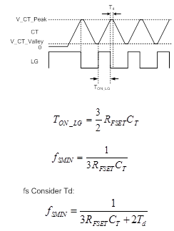
Dead time is a key variable that admittedly is omitted in the datasheet. This is the main cause for the difference between calculation and measured results. I illustrated the reason with the following figure. The CT voltage is held in dead time, so the actual frequency is lower than calculation.
Of course, that makes perfect sense. Thanks for the explanation!
Since I’ve measured the frequency with the chip in a stand-alone situation (so without a switching bridge), the HBVS pin is is of course floating, so, according to the datasheet, HR1001a will introduce a nominal deadtime of about 350ns. When I add this information to the fmin calculation, I get a value of 86kHz, which is almost bang on my measured values.
I’ll also add this feature to my spice model of the oscillator to improve my simulation accuracy. It might be a good idea to add this info somewhere in the datasheet, or in a separate technical note.
Thanks again for the support, this has made things a lot clearer!
P.s. I’ve also seen the HR1002a controller listed on the website. I’ve applied for a myMPS+ account to access the datasheet, but could you inform me of the main differences between HR1001a and HR1002a? Will this part be a pin compatible replacement?
The Frequency shift threshold Vcs-OCR has been increased from 0.78V to 1.0V in the HR1002A. However the OCP threshold is kept the same. Also the Maximum dead time has been increased to 1.5usecs. The Gate drive source and sink resistors have been increased to 5.5 Ohms and 2.8 Ohms. We are finding out from the factory if the HR1002A is pin to pin compatible with HR1001A. We will let you know as soon as we get an answer.
Thanks for the info. I’ve had a look at the datasheet for HR1002a and it looks to be a pin-compatible part. HR1002a does have a pulled pin between high and low side drive, but that should not be an issue for production.
The only major difference for us would be the OCP function. On HR1001a this is self-resetting, on HR1002a this is a latched function. This is generally not desirable in audio systems, so for now we’ll just continue on with the HR1001a, this chip seems to have all the bells and whistles I would like for a voltage/frequency mode LLC controller.
I’m happy to hear that the HR1001A fits all your needs. For further technical assistance, you can contact one of our remote support FAEs through MPS Now. For more general questions on this topic or a new one, we welcome you to continue contributing to the forum.