Hi, evaluating the above for use on advanced lighting controller.
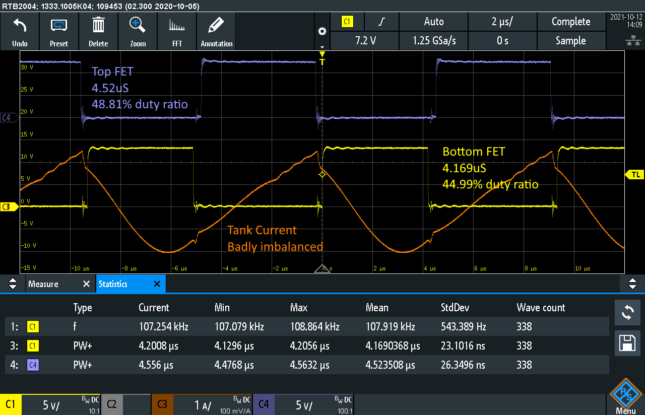
Running at 54V/2A and 108kHz we have severe tank current imbalance and corruption.
This is due to the top drive being on for 350nS longer than the bottom drive. This occurs on BOTH parts.
Typical figures are 4.52uS vs 4.17uS ( 49% duty ratio vs 45%).
Imbalance creates higher peak currents, more heat, more voltage ripple, so I need to understand how to improve this. Some difference in times is expected but not 350nS.
Our transformer has integrated leakage which is very well balanced (within 0.5uH)
Turns ratio is 16:4+4. Primary inductance is 234uH. Primary leakage inductance is 38uH with either secondary shorted. resonant capacitance is split rail type with 2 x 22nF.
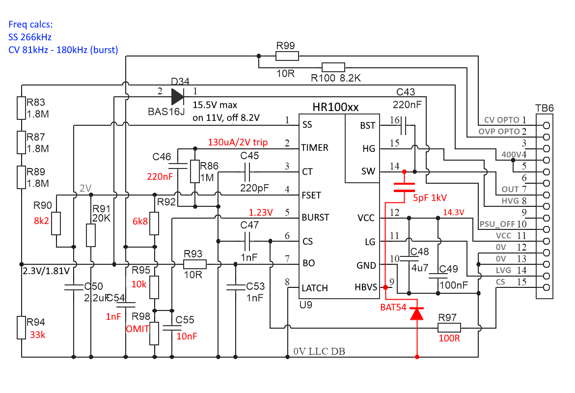
I enclose our LLC control board schematic.
Dead time appears about 320nS.
What appears to be a solution:
The sensitivity of FSET pin is a major factor. After intensive theorising, looking at connector TB6, it was found that a tiny capacitance of just 0.3pF between ‘OUT’ pin 7 (SW) and CV opto pin 1 could corrupt the switching times as witnessed.
The PCB tracks from these two nets on the MAIN PCB (LLC control board is plug-in) were too close. The capacitance would link through to FSET pin via R99 and R92.
When main board CV Opto track was removed and replaced with a wire routed away from SW track, the imbalance all but disappeared. A very rare case of practise following theory!
Recommendation: Protect FSET pin from interference at all costs!