I used Hr1001 to design 160w power supply but i have a problem in output voltage and switching frequency ,the output voltage was expected to be 16V but the measured value is between 20 :26 v changing with input voltage and the switching frequency does not change its value its constant at 190KHz despite changing input voltage
how can this problem be solved
The LLC regulates output voltage by altering frequency. Higher frequency gives lower Vout.
I suspect you are stuck at the maximum frequency and Vout is too high and there is no regulation because you are stuck. What is going on at the optocoupler output? If Vout is too high then U2B should be almost at ground.
I used PC817 ,it reads 1.1V on led and 0.1V on Vce
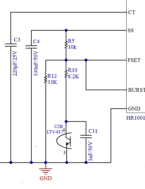
the voltage of CT pin is 1.99V and 2.2V on Fset ,I think it is reasonable compared with simulation results
Is there any layout restriction regarding Fset components?
Fset is supposed to be 2.00 V 2.2 is a big miss. The voltage on the CT pin should be a triangle between 0.9V and 3.8V so neither of those voltages seems correct. I would be putting the Fset components right near the IC. The most critical item will be the CT cap though.
I will repeat measurements on oscilloscope ,
these values on timer pin can cause any faults?
I found that the circuit is actually stuck at Max frequency and tried to change values of Fset resistor but still getting same output .the voltage on Fset is 2V but having a spike of 4V at the max frequency ,also the voltage on CT is triangle reaching 4V . any suggestion?
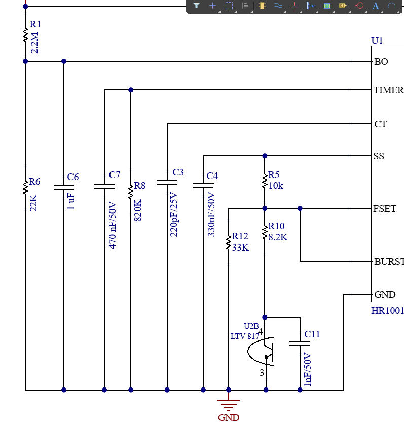
Hi mariam-shalaby,
Please provide an updated schematic of how you are connecting the part, showing each component value clearly. Also, provide scope captures on the voltages on the input and output pins.
Then we can start debugging from there.
Thanks,
Cindy