Please understand that I am asking questions through a Korean translator.
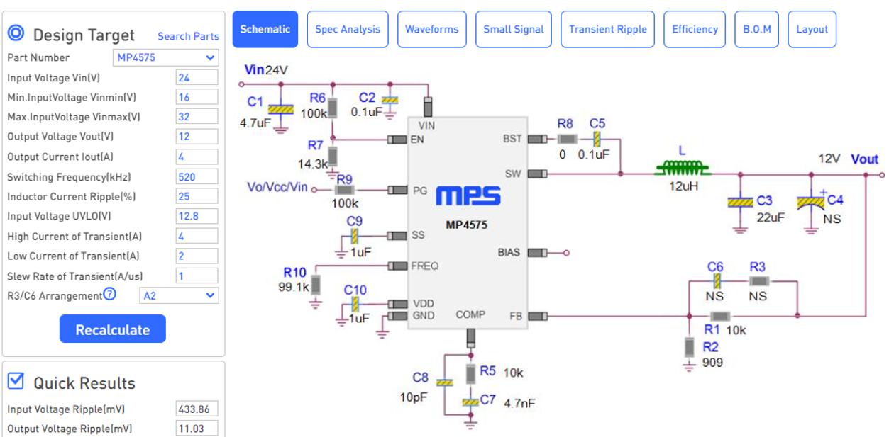
I’m designing Buck converter with MP4575 with online design support
According to the Iout and Inductor riple current (%) settings, the changes in C8, R5, and C7 connected to the COMP pin were confirmed based on Online Schematic.
By the way, I want to know about the calculation formula that sets the value and the change in MP4575 behavior according to the values of C8 and R5+C7.
Hello @eunsung8910 ,
Equations and steps of how to calculate type 2 compensation values can be found under “Compensation Components” on page18 of the datasheet.
We recommend following the design values on the evaluation board.
Hope this helps!
Regards,
Jonathan
Thank you for your kind reply.
Thanks to you, I was able not to go past the content.
I have one more question.
I’m trying to design MP4575 in Step-down form to get an output voltage of 12V, but if the input voltage is 13V to 10V, FeedBack will not reach the set voltage, so I wonder if I can judge it as VIN = VSW = VOUT in that case.
If a requirement is added to compensate for the case, you have a plan to connect the MPS Step-up Regulator to the back end of Step-Down Regulator Vout.
Hello @eunsung8910 ,
The MP4575 can only step down voltages, the part can only take your Vin and make it lower. The MP4575 does not have 100% duty cycle, so Vin must be greater than 12V for Vout to be 12V. If you need to get Vout of 12V with a Vin of 10-13V, I recommend looking into buck-boost converters.
Regards,
Jonathan