Hi,
I’m trying to implement the control algorithm for the MP2731 depicted here, but once VIN_STAT in register 0Ch changes to 001 (non-standard) when the solar panel’s output voltage raises, it does not go back to 000 (no input) when the solar panel gets completely dark, not even disconnecting it from the MP2731.
How can I detect the input is no longer available?
BR
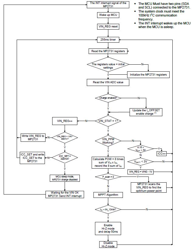
Well from the flow chart it looks like if the panel sources less than 17mA ( i.e it is dark) then it kicks back to some initialization phase. Or if the panel voltage falls below the Vreg voltage. Have you seen this behavior on an actual panel? It would be hilariously bad it the solar solution only worked for one day. I am not saying you are wrong. This is the sort of thing that can slip through. At night the solar panel goes hi-Z so if the power converter doesn’t turn off there will be some loss backwards through the panel but maybe not enough for a harried apps engineer to notice.
Hi @jshannon,
Feel free to say I’m doing it wrong, that’s just a fact ;).
I don’t notice the controller kicking back to an initialization phase, the registers I modified keep their values until I reset the controller and do not revert to their default values.
We have a diode in series with the panel, leakage through that path should be minimum, IMO.
I’ve been for decades now developing hardware and software, so I’ve often seen prototypes showing odd behaviours. I will try with another board for just in case something went wrong with the one I’m using for development.
Just as a side note, some revision/improvement works on the datasheet will make our lives easier, especially with new online customer-support models and paradigms.
BR
Oh I was misreading the flowchart. It should kick back every 250msec or so. if the flow chart is to be believed the registers you wrote to should be reset. Maybe not all registers are reset? this is really a question for an apps engineer. On a side note, I would be tempted to remove the panel diode to see what happens. The power of the panel will increase by the amount you were wasting in the diode, i.e Impp X Vdiode extra power. The catch is the power converter has to then act as a diode at night, and I would hope it could do that.
The 256ms box represents a timer, a cyclic processing after a good power source has been detected. After the input is no longer valid, the algorithm indicates that the host should wait for a power OK detection. That detection can be done manually, by periodically reading the status registers, or by letting the controller just to interrupt the host.
To my best knowledge, the registers are reset when all power sources (battery and input) are no longer in specs, POR in this case, when the watchdog expires, or when manually reset by writing to the REG_RST bit in register 01h.
Theoretically, the device incorporates a reverse blocking FET (Q1), but specs are clear in specifying -0.3V (to ground) minimum input voltage, absolute. This means it is mandatory to add external reverse polarity protection/blocking circuitry. Our device has strict requirements in terms of protections and mitigations for high energy surges entering the system from the solar cell, it is to be installed near to sources of very high-energy magnetic an electric-field impulses.
FYI, @jshannon, after trying with another prototype, where the input detection worked OK, I resoldered the chip and some components in first prototype and it worked OK again.
But in what I’m still having issues is in How to properly control the MP2731 and its interrupts.
BR
Well good luck, that is some kind of digital stuff