Hi,
I am using MP2615C to charge a 1 cell 18650 lithium ion battery. I set SEL to ground and CELL to high. According to the datasheet, the charge terminal voltage should be around 4.2 V. But I can only charge the battery to around 4.05 V. I tested multiple battery pack.
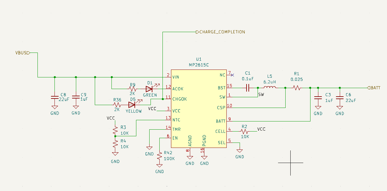
Here is my schematics
How should I debug the issue?
Thanks!
Hello,
According to your schematic and the datasheet:
- CELL to VCC enables single cell applications, which you’ve done.
- SEL pulled low or floating Vbatt is 4.2V per cell, you’ve also done.
So Vbatt should definitely have a charging voltage of 4.2V. I would first recommend starting with checking the voltage of the BATT terminal verifying that it is at 4.2V.
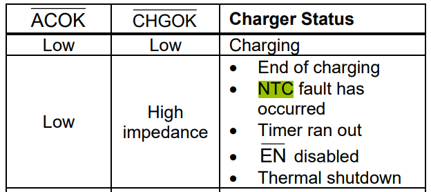
If this is the case, I would check the charging status in accordance to Table 1 below:
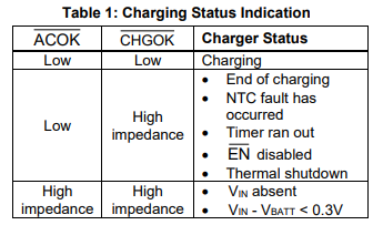
The nominal voltage of your 18650 Lithium Battery should also be checked in conjunction with the status of the ACOK and CHGOK pins. It could be possible you have fully charged these batteries and the nominal voltage of them would be 4.05V.
If there are any more questions or if I have misunderstood anything, please reach back such that we may solve this problem.
Hope this helped,
Krishan
Hi Krishan,
Thanks for the reply. The battery cell we are using is LG MJ1. The protection circuit sets the limit at 4.2 V. And I can use other charger to charge it till 4.2 V. So the battery should be good.
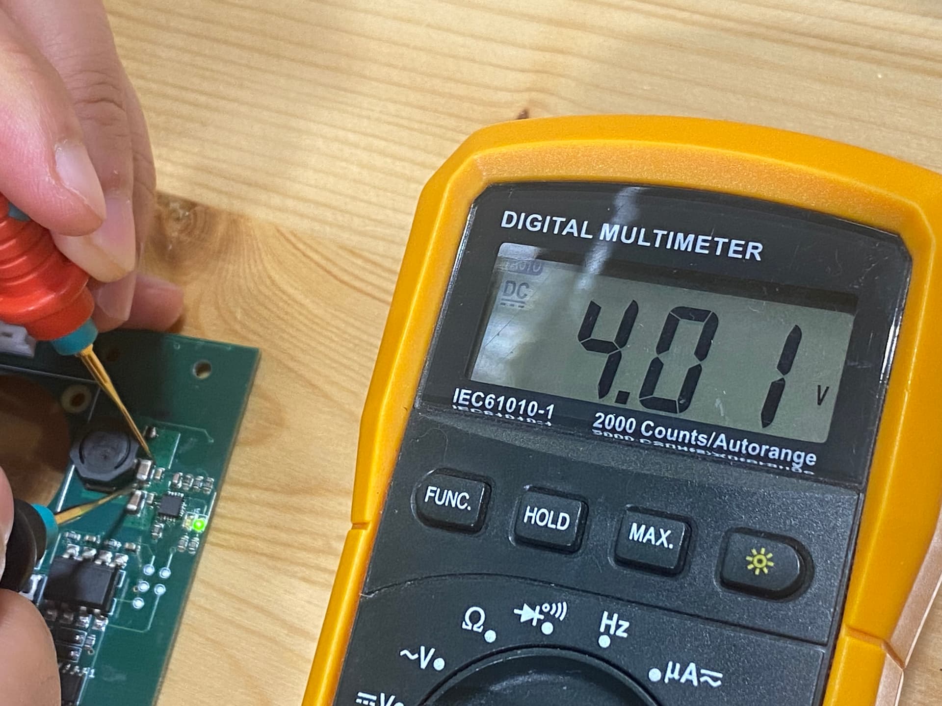
See attached image of my prototyping board, the BATT terminal shows only 4.01 V and the charging already stopped. See the LED connected to CHGOK is off.
What do you think?
Thanks
Lincoln
The recharge threshold for this battery is 4.0V. So the charger sees vbatt greater than 4V and says hey it is charged.
Have you tried this starting with a depleted battery?
jshannon brings up a valid point, but the fact that you said that this battery charges up to 4.2V and the BATT pin only goes up to 4.01V is definitely fishy. I am sure that a depleted battery will charge and is worth trying just to test charging functionality.
However, your LED configuration corresponds to ACOK being low (LED ON) and CHGOK being high impedance (LED OFF). The nomenclature of the LEDs being on and off is odd in the datasheet I will acknowledge that.
According to your schematic, the EN pin is certainly enabled and the TMR pin is grounded and therefore not being used.
I noticed that you don’t have a 1uF bypass capacitor between the VCC pin and AGND as seen in page 3 of the datasheet.
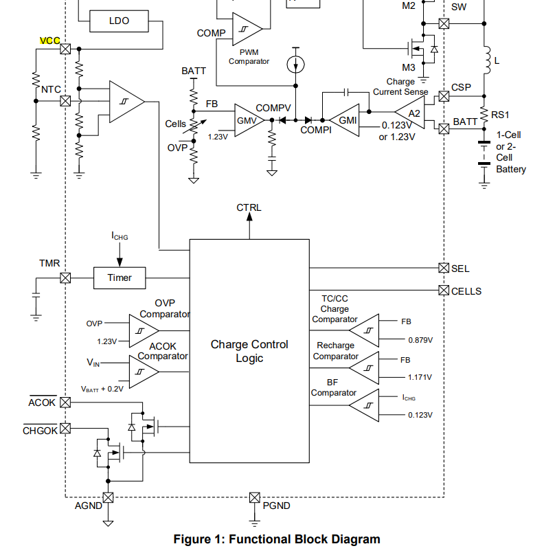
I don’t think this is the contributing issue, but the VCC output does directly connect to the charge control logic as seen in page 12 of the datasheet. So, it could affect things downstream at higher voltages (in your case (at 4.01V).
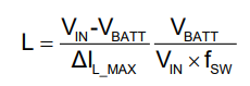
Also, it would be helpful to know your switching frequency and input voltage as these variables relate to Vbatt using the following equation as seen in page 17 in the datasheet.
I know I’ve thrown a lot at you, but I hope these steps help solve your issue.
Best,
Krishan
Hi Krishan,
It seems the 1uF does the trick. I manually added it to the board and a battery is finally charged to +4.15V.
I will charge a couple more battery to make sure.
Thanks
Lincoln
1 Like
Hi Krishan,
I tested 3 more batteries and they all charged to >4.16V. So the 1 uF seems fixed the issue.
A quick question may not be relevant to this thread. I am currently using 5 V as input voltage. Will it charge quicker if I put in a USB C PD controller and increase the input voltage to 9 V or 12 V assuming the adapter is still capable to provide 2.1 A?
Thanks
Lincoln
Glad to hear that adding the capacitor fixed your issue.
As for charging your battery faster, I don’t think increasing your input voltage will make it charge any faster, especially when you are preserving your 2.1A output current and output Vbatt of about 4.2 (or >4.16V). In this case, increasing the input voltage would only decrease your input current.
The only way that your batteries would charge faster would be if you increased your output power, which means increasing your output voltage (which you have done by adding the 1uF capacitor, increasing your voltage to >4.16V). If adding a USB C PD controller helps you do that, then your batteries would certainly charge faster.
Of course, with that being said, it would be best to double check the current rating thresholds of your batteries. The typical charging voltage is 4.2V and the maximum charging current of the LG MJ1 18650 battery is 3.4A in one hour given that the battery is 3400mAh. If you are open to it, this would be a better suited part to your specific application.
MP2617B | 3A Switching Charger with NVDC Power Path Management For 4.2V Single Cell Li+ Battery | MPS (monolithicpower.com)
Hope this helped,
Krishan
1 Like