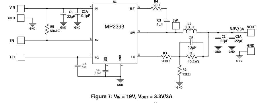
Could you provide guidance on how to properly integrate an LED with the Power Good (PG) signal in this schematic to monitor power-up behavior? Specifically, how should the LED be connected (anode, cathode, and current-limiting resistor) and what values are recommended? Additionally, could you confirm if the described LED behavior is correct: the LED should remain off when the PG signal is low (e.g., during power-up, undervoltage, overvoltage, or protection mode) and turn on when the PG signal is high, indicating stable output voltage between 92% and 120% of the internal reference?
Also, could you explain why a separate 22µF capacitor is used on the Vout pin instead of a single 44µF capacitor? What are the considerations behind using multiple capacitors versus one with an equivalent total capacitance?"
In order to integrate the PG signal effectively, you will want to set your LED in an active low configuration where it turns on when the PG signal is high and off when PG is low.
Connect the anode side of the LED to a positive rail like VCC or Vin. Next, connect the cathode to a current limiting resistor that should be adjusted to the proper voltage and current settings of your LED.
Typically, LEDs will need a voltage of 2V with a current of anywhere between 10mA - 20mA. To size this current limiting resistor, here is an example assuming Vcc = 5V, Vled = 2V, and the LED current is 10mA.
R = (Vcc - Vled) / I = (5V -2V) / 10mA = 300 ohms.
Again, this should be adjusted to the actual measured value of Vcc, the rated LED voltage, and rated LED current.
Also in terms of using separate 22uF capacitors as opposed to a single 44uF capacitor:
- The parallel combination of the two capacitors reduces the overall ESR, improving transient response, stability, and slightly on efficiency. This is why most MPS typical applications utilize this.
- Smaller capacitances generally respond better to higher frequencies supported by Zc = 1/jwC, further supporting the use case in stabilizing Vout.
- Finally, two smaller capacitors can usually be cheaper and smaller than one bigger capacitor, saving on money and board space.
Hopefully this provided some insight.
Best,
Krishan
1 Like