I see from the schematic the EN is not being pull up above 1.55V, If you check the EC table, the rising threshold for EN is 1.55, so the part is turned ON and works as designed.
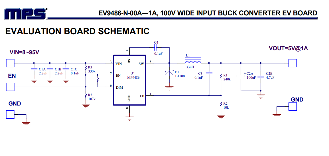
Have you tried a demo board? I see why you didn’t connect the EN to anything, the datasheet clearly states that there is an internal pullup on the pin, meaning you don’t need to.
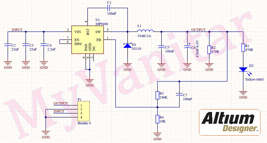
What is the saturation level of you inductor? I would pick one of over 3A. I notice that you have a much larger output capacitor than the reference design, I suspect that may be your problem.
This is a kind of sketchy operation, the DC out is set by the output voltage divider, but operating frequency and ripple voltage are set by the C6, C7 R4 set of components. Plus in fact C elsewhere as well. Consider the effective impedance of C7 at say 100khz it is about 16 ohms, versus the parallel resistor of 240k. So the AC operation is determined by the ripple voltage on the output coupling through the C7 to the FB pin. If you choose low ESR output caps, or large values, you will reduce that output ripple voltage ( you would think) but since the system is essentially an output ripple voltage regulator what will happen instead is the frequency will go down and the output inductor will saturate, forcing an early termination to the switching cycle and insufficient transfer of power and a too low output voltage
So I suggest lower output cap values, like in the demo board.
Thanks for the reply sir
if EN is no need to connect then why mentioned Evaluation Board and you are talking about C6 ,C7 R4 according to datasheet right ? just to confirm.
I’m attacking the video clip to show the result
same i followed the evaluation board schematic
but still current is not deliver properly
input 30 output 5.2v BUT NOT ABLE TO DELIVER CURRENT PROPERLY see the video clip here https://drive.google.com/drive/folders/1JngGF7PF8oj03PbwjVJC1DA6R9yXEzma
I think I was referring to your ref designators, the end result of my stream run on explanation was I think you have too much output capacitance. That is the biggest most obvious difference with the demo board as well.
Hi Sir Thanks You so much for you reply okay understood I’m following the above circuit but still the output volt is 5v but not 1A current I’m facing the current issues please help so solve this issue.
Do you have the specification of the 33uH inductor? That looks kind of small to support 1A, also after seeing the video, I have to say your components are quite different from the demo board components.
The other point is can you first test on a 5 ohm resistor a known 1A load. The servomotor may draw much much higher inrush current as it is starting up.
Hi Thanks sir
okay but its not able to run our simple GPS tracker device which consume less then 1A or if there is any other ic which deliver up 3A for our application please share the part no and datasheet
I am suspicious of your component selection, electrolytic caps have quite different performance characteristics than ceramic caps. I suspect your problem is not the IC but the components surrounding it. I would suggest trying to obtain a demo board and see if that works, if it does, copy the demo board.
I am sorry, I can’t do that, it looks to me like you should be yelling at someone who works for MPS. Their parts are OK but it looks like they fall down supporting the little guy. Do you have a local rep? Or have you tried MPS now? I would suggest swapping in parts from the demo board BOM to see what happens.
Just caught wind of this thread and wanted to check in with your design and see if things are working. Did using the demo board for this application end up working for you?
(also @jshannon I am new but will try my best to support people around here like you have. Thank you for your contributions on this forum)