Hi,
I am currently trying to drive my 24 volt BLDC motor with the EVQ6532-V-00A board, which has the MPQ6532 pre-driver on it. The datasheet for this board has 5 steps to get started with the board. and I did all of these. I connected my 24 Volt power supply and the GND, I Connected the VH and VH_Gnd which is around 3 Volts (due to microcontroller, I set OC_ref to 0.5 Volt, and later changed that to 1.5 to see if it changed anything, I connected the hall sensors and checked if they are working and I connected my PWM signal to the dedicated PWM pin.
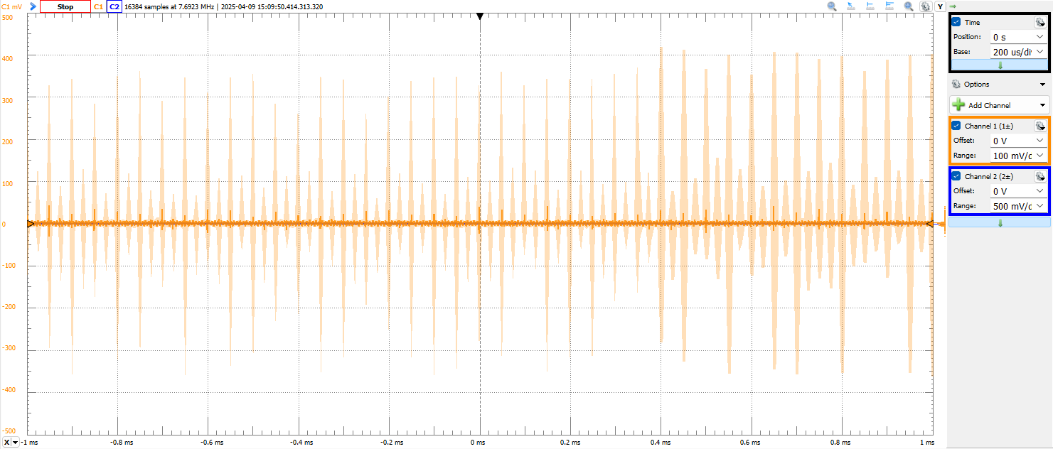
When turning on my power supply, my U, V and W windings of the motor (HAD, HBD and HAC on the board) are permanently 24 Volt, even when I am sending a PWM signal. The PWM signal has a frequency of 20 kHz. The board draws only one milli Ampere from the power supply in this state, which increases to 4 milli Ampere when I send the PWM signal, so something is definetly happening.
I already tried pulling the nBRAKE pin high to disable break mode, but that didn’t affect anything. I pulled the switch that disables sleep mode down as well, so I’m a bit lost on why it doesn’t work. Could you guys have an idea of what my issue is?