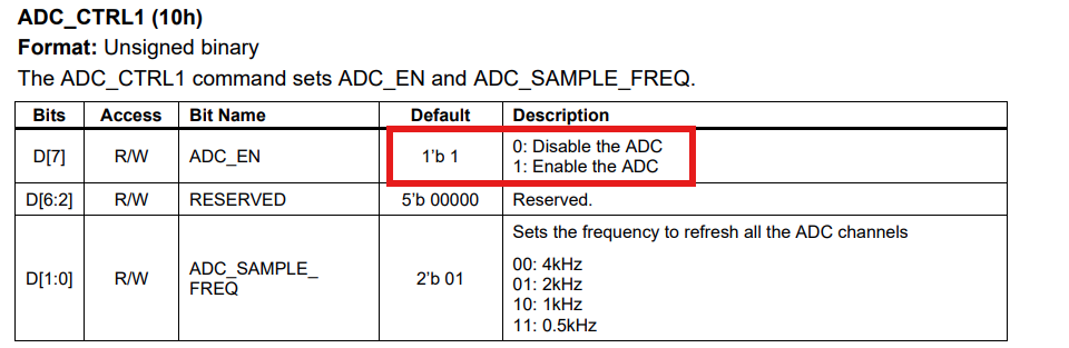
I was testing the boards EVM54322-PB-00A in mode 3 to monitor by I2C bus the ADC sensor but those didn’t work, so checking the register ADC_CTRL1 the D[7] bit of ADC enable was “0” but according to MPM54322 datasheet of the default value is “1”, what is the correct default value?, I had to write this register to enable the ADC functions.
I was using the board by default in mode 3, as I said when I connected at the output of the board a device with power consumption of 1W reading the sensor those always reported 0 values at that moment, the ADC sensor was disabled according to the ADC_CTRL1 (10h) register with value “0” in the bit 7.
To solve this, I had to enable the writting function changing the register the bit 7 of the LOCK (00h) register and the change the ADC_CTRL1 (10h), after this the current sensor has been working reading the register IOUT1_ADC (13h).
I wonder if there was something else that was done to change the value of this bit. Even register 00h should have been set to 1b’1 by default. How are you interfacing with this module?
I’d like to mention that we received TWO new EVM54322 today. On both, out of the box, we saw defaulting to ADC Enabled = 0 (IE Disabled). We are connecting by EVKIT-USBI2C. Using the jumpers to select Mode 0.