Hi,
I would like to use current sensing for implementing FOC control of my BLDC motor. To implement this in my current setup I need to know the shunt resistance and op-amp gain used in the EV6540. I’ve looked at the schematic but need help understanding it.
Questions:
- Is there a shunt resistor? Or do I need to include one outside of the board?
- Is there an op-amp used for the current sensing outputs? If so what is the gain?
Thanks,
Frank
Hi Nouman,
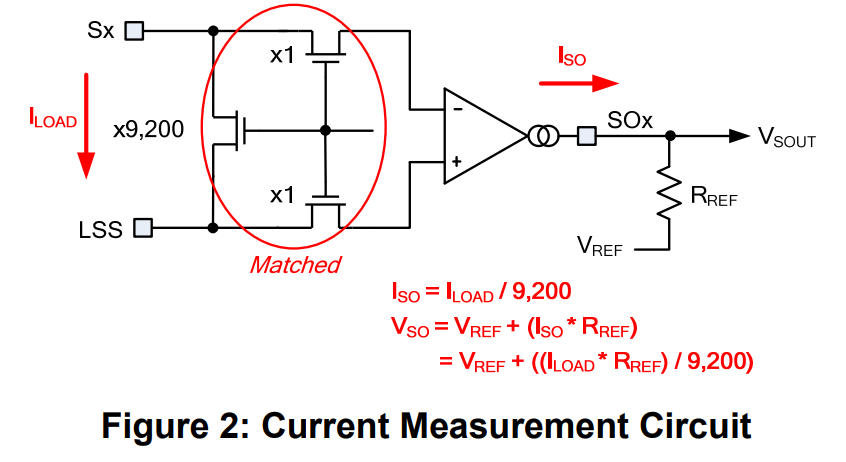
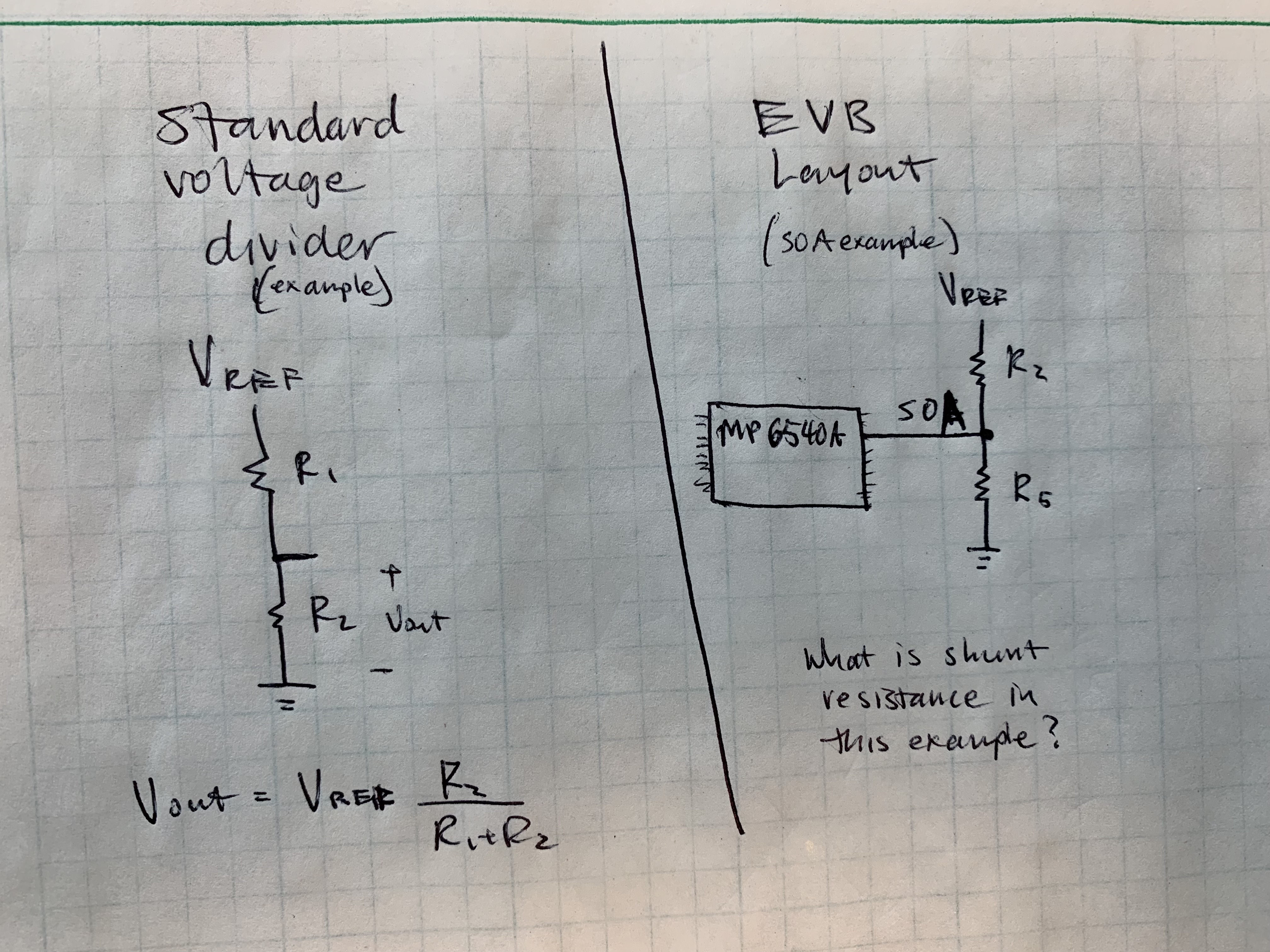
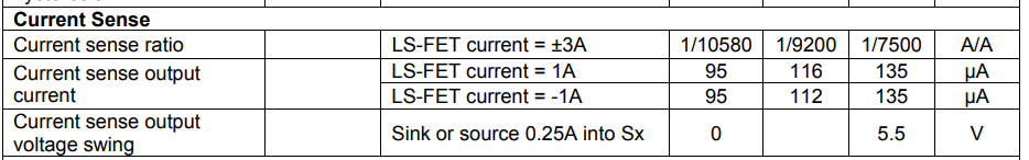
Thank you for your detailed response. The gain makes sense (looks to be 9200 based on the diagram). The shunt resistance is tripping me up – the layout is not of the voltage dividers I am familiar. The diagram helps explain my issue – in this case what is the shunt resistance? Forgive my inexperience in this area.
V/R,
Frank
Hi Frank,
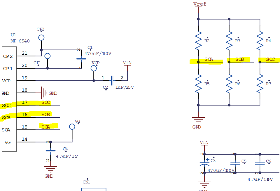
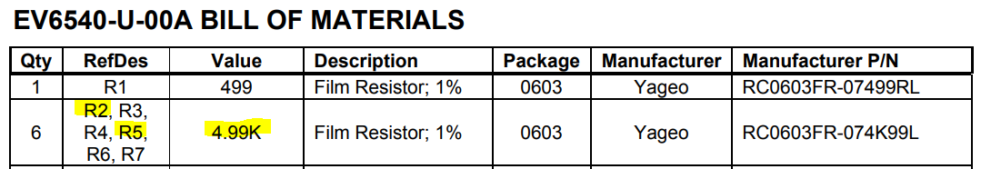
Thank you for providing a capture. Rterm is an equivalent resistance in this case for the voltage divider as you have also presented. R2 & R5 along with the other 4 parallel resistors are all 4.99kohms in value.
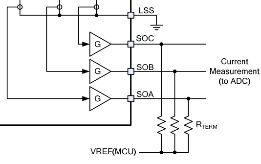
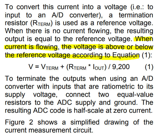
Rterm is used for converting the current to voltage for ADC supply.
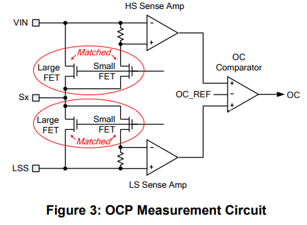
Did you need this shunt resistor for over current protection? There is OCP built into the MP6540 gate driver circuitry.
I would like to clarify my understanding of your question on shunt resistance on the eval board.
Hi Nouman,
Thanks again for your response I appreciate the help. The overall goal is measure current from the MP6540A. I will use this current measurement to commutate a BLDC motor.
To accurately measure the current I need to know the shunt resistance. The microcontroller is measuring voltage on an analog pin. To convert this voltage into a current, I need to come up with a voltage to amps ratio gain – this gain value is partly determined by the shunt resistance. The shunt resistor is used to measure voltage drop across the resistor, which the microcontroller can sense on an analog pin.
My question restated is: what is the equivalent resistance between the MP6540A SOa pin and the SOA test point on the Eval Boar. (I understand it will be the same equivalent resistance for SOB and SOC).
Thanks again,
Frank
Hi Frank,
Thank you for elaborating further, I appreciate it.
With regards to your question, since R2 and R5 resistors are the same value of 4.99kohms, the voltage at Vout will be 1/2 of Vref. (referencing your drawing)
Although there is a parallel resistor implementation, You can try utilizing a shunt resistance value of 4.99kohms for Rterm. Per the highlighted portion above, since the voltage can be above or below Vref.
Regarding Current Sense, I will add a capture on the sense ratio to help further.
Kind Regards,
Nouman