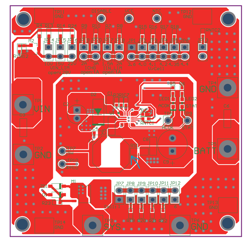
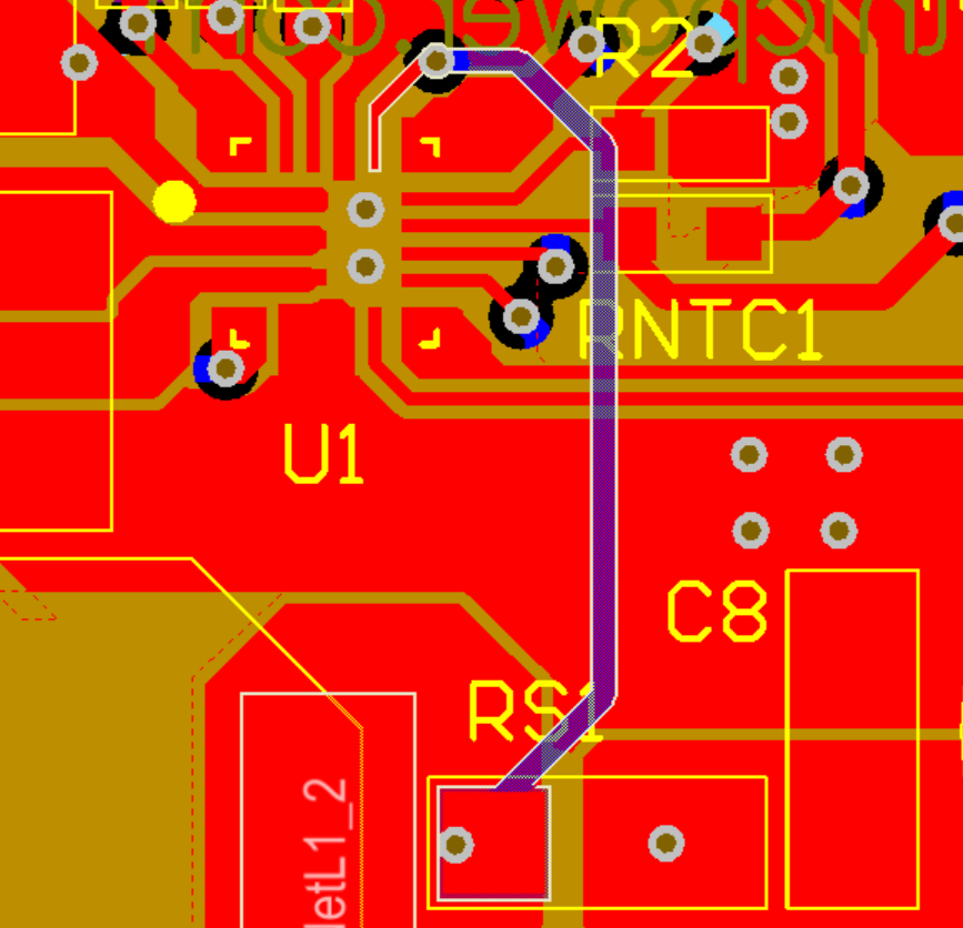
I have successfully used the EV2759 to charge a battery. I’m working on implementing the eval schematic and layout into my design. I noticed that in the eval layout, there is at least one connection missing for the sense resistor. Is there a more up-to date example layout? I don’t want to base my design on an incomplete or old design. You can see there is no connection (blue arrow) returning to the chip. The connection does exist on the physical eval board.
Also for anyone looking at this the Bottom layer is mirrored LR in the eval datasheet.
Hello @jimmy1 ,
The schematic and layout for the EVB are provided under Design Resources.
The design files currently provided have all the connections the EVB has:
Regards,
Jonathan Hidalgo