I have a buck converter running at 650kHz, 12V output voltage at 10A max and an input voltage range from 35V to 60V. As the inductor I chose the SRP1238A-4R7M, mainly because of its low profile because the hight is restricted in my application. During tests I noticed, that the efficiency is not as well as expected:
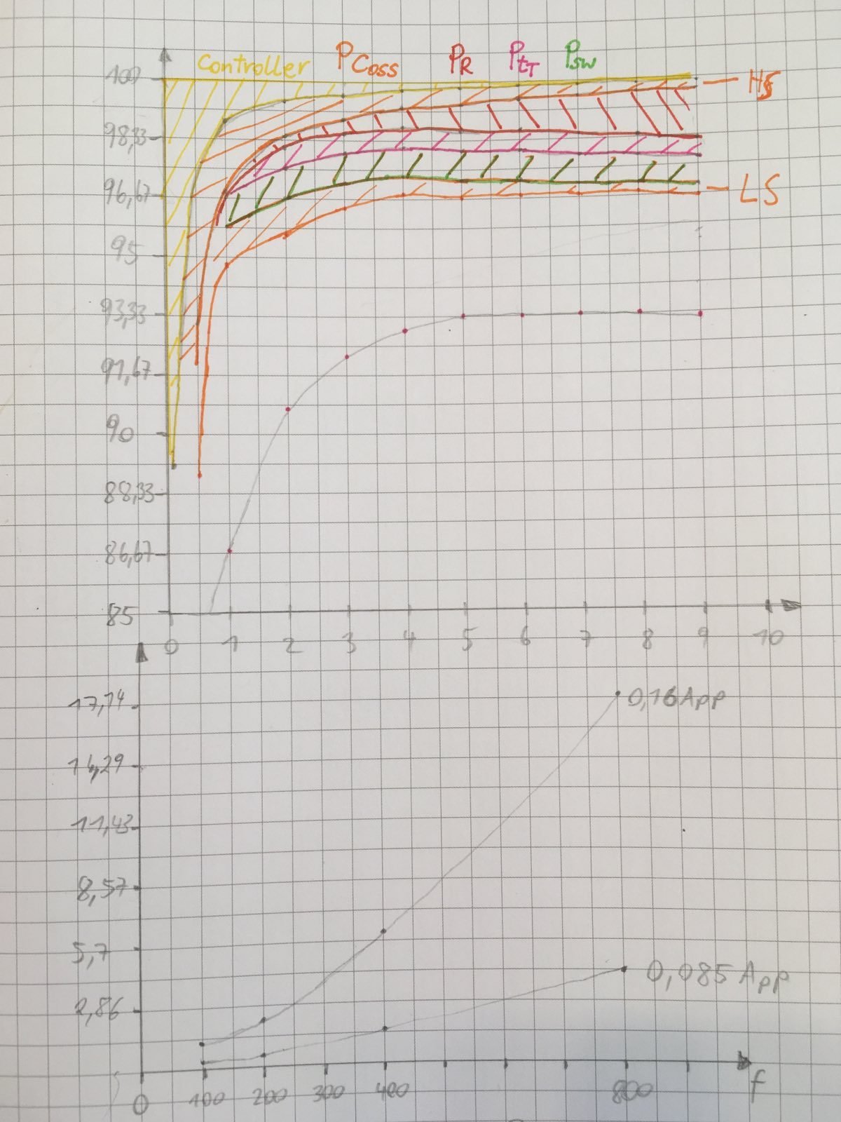
The top graph shows the efficiency at 45V input voltage, I also marked several different loss components and it can be seen that about half of the losses are unexplained. The only obvious components that is not considered in this graph are the AC losses of the inductor. To check if all this missing power is dissipated in the inductor I measured the power loss (mW) in the inductor used at different excitation currents and frequencies (see the lower graph). From this graph one can calculate an AC resistance of 4 Ohms at 650kHz. Considering 3,5App ripple current, which is about 1 A AC, this means that about 4W are dissipated in my application, explaining the missing losses and the poor performance.
I also dissected the inductor and learned, that there are 8 turns wound at 4 layers. Applying Dowell’s equation, this equates to an AC resistance of approximately 1 Ohm, so 3/4 of the power loss must be due to the carbonyl powder core.
Therefore I came across your inductors and the buck selection tool. I appreciate that your datasheets give more information on the HF behaviour than most but I am still unclear how to estiimate the losses for a given inductor. From your datasheet I can read a certain impedance as a function of frequency. Do I need to multiply that value with my ripple current squared to get the power loss? This however would imply a constant power loss since the ripple current is constant throughout the whole output current range (in CCM mode). This cannot be observed. Am I right that core losses are also dependent of the DC current? Where can I get info on that behaviour?
So my final questions are the following:
How can I estimate the inductor power loss in such a buck application?
What is the ideal core material for such a frequency?
What is the ideal geometry for such an inductor and is it sossible to get flatter without increasing the AC resistance?