Dear MPS people,
I have written in another post, but received no word from you, so I thought it would be a good idea to start a new post
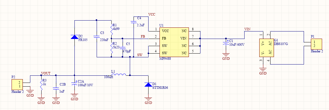
Anyway, I designed a 5V/100mA power supply as per schematics
The inductor used is SRN5040TA-101K (
Bourns® Inductive Components).
R2 is actually 5k1.
My desired Vin is 9.5 - 270V.
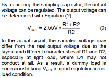
Can you please verify this design? For the time being, I can tell that my measured output voltage is not
5V at no load, but ca 4.7V.
In the other post I reported that MP9488 burnt when I unintentionally increased the input voltage over 300V. I suspected that it was because I tied the N.C, pins 5, 6 and 8 to Vin. Do you have any comment on this?
Many thanks in advance
Hi vladimir.rajovic,
Please see the equation on Pg. 12 of the datasheet for setting the output voltage. I used your feedback resistor values and got an output voltage of 4.98V. The datasheet notes that there will be some variation in the real circuit, so I would suggest just slightly altering the resistors if possible.
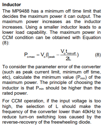
I do not recommend that you connect the NC pins 5, 6, and 8 to the input. Please leave those pins unconnected, as noted on Pg. 9 of the datasheet. Lastly, please use this equation from Pg. 15 of the datasheet to verify the size of your inductor.
Hi mpsnow.bryan. Thank you.
Regarding the equation (8), can you confirm that I should take 0.64A for Ipeak and 13.1us for tminoff?
Also, please note that in Fig. 8 of the datasheet the pins 5, 6 and 8 are connected to Vin. If this is not good, the datasheet should be updated I guess.
Regards
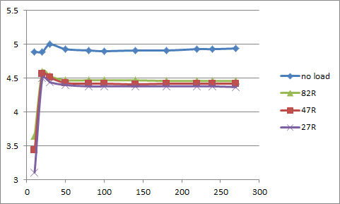
Meanwhile, I made some measurements, and here are the results:
vout(vin) for different loads with a 100uh inductor:

For loads of 27R and 47R I could not get stable output for higher input voltages, the IC kept restarting
vout(vin) for different loads with a 1000uH inductor:
I must say I am pretty disappointed with the regulation, please comment.
Thank you