Hi all,
I am exited to join this community and psot my first topic.
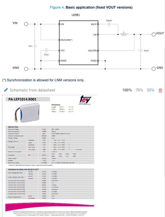
I selected the L6981C50DR for my DC DC buck converter with the following external components and schematic for my application:
- Cin: GRT31CR61H106KE01L Multilayer Ceramic Capacitors MLCC - SMD/SMT 10 uF 50 VDC 10% 1206 X5R AEC-Q200 RoHS Compliant
- CinA: GCM31CR71H105KA55L Multilayer Ceramic Capacitors MLCC - SMD/SMT 1 uF 50 VDC 10% 1206 X7R AEC-Q200 RoHS Compliant
- CvCC: same as CinA
- CBoot: GRT188R71H104KE13D Multilayer Ceramic Capacitors MLCC - SMD/SMT 0.1 uF 50 VDC 10% 0603 X7R AEC-Q200 RoHS Compliant
- L: MSS1038T-333MLC Power Inductors - SMD 33uH Shld 20% 2.3A 93mOhms AECQ2
- Cout: GRJ32EC71E226KE11L Multilayer Ceramic Capacitors MLCC - SMD/SMT 22 uF 25 VDC 10% 1210 X7S
My system is powered by a smart battery and I want to use the converter to convert the typ 12.8V from the smart battery to 5V to then feed it to the esp32-c3-devkitm-1. Experimental values showed that the output current is at around 120mA with spikes close to 300mA, I used Iou_max = 500 mA in my calculations to determine the capacitance for the input and output capacitors and also the inductance.
Could you please verify my selected values for the inductor and capacitors (part numbers taken from mouser) ?
Now I am proceeding with the layout of the PCB on which I will assemble all the parts, could you please suggest a guide or do you have some advices regarding the desing of the PCB?
I am new to this field and especially power modules design area, any remarks or advices would be highly appreciated.
You do know that that chip is made by ST? Find a close equivalent MPS part and pretend you are using that, then ask the question again
I am sorry but why is this relevant to my question ? are community forums from certain manufaturers only discuss their components ? I am fairly new to posting technical questions in forums related to engineering, is this a rule of thumb ?
But my solution then would be to move to ST’s community forum instead.
Now I remember why did I come here instead of going to ST’s community forum, I asked initially in stack exchange in the electrical engineering branch and one of the repliers suggested a link that spoke about inductor saturation and how to design for low EMI which are links from MPS which then brought me to here.
I will attach the link to the post I am referring to.
I wouldn’t expect an MPS engineer, paid by MPS to help you use an ST part where you could be using an MPS part for the exact same function. Who knows? You might get lucky.
Then I did not see the difference between open community forums, which are independant of the manufaturer and actually focus on the issue and how to fix it, and community forums in manufacturers websites who are, like you said, paid by those manufacturers so they are only interested in their components. Again I appreciate any helpful criticism. Thank you for your follow ups and maybe in the future if I went with an MPS component you will most likely find me here.
Hello Anis, apologies for the late reply!
While jshannon brings a good point in terms of MPS not being able to directly support the L6981C50DR, but I can help you in a general sense with an equivalent design example using an equivalent part (like the MP4312) and answer your questions by showing you how I would check the things you are asking for.
For MPS parts like the MP4312, we have our DC/DC designer tool, which incorporates the sizing equations for the input / output capacitors, inductor sizing, compensation network recommendations, bootstrap capacitors, and many other significant characteristics.
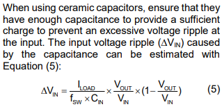
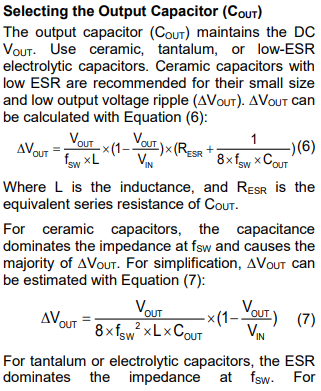
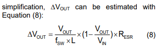
I am not sure if ST has something like this, but here are some notes on the component sizing from the MP4321 datasheet that I think are generally helpful:
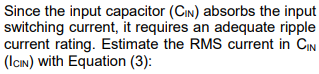
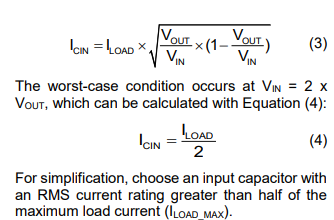
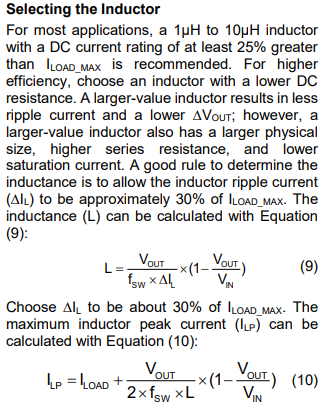
Everything that I have showed you here is basically general sizing equations that you can manually check if software like the DC/DC designer is not available but is also great to know when you are just starting out. Be wary of the voltage ratings for each of the discrete part you have selected on Mouser.
For the Vcc capacitor, I would say that a general rule of thumb is that it would generally be 10x bigger than the Cbst capacitor if you have one. You will need to check the ST datasheet for specific recommended values to get a better idea on a rule of thumb.
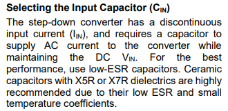
As for PCB layout guidelines, the following is from the MP4312 datasheet, but may very well be helpful for general applications:
This information is certainly applicable for any DC/DC converter.
Best,
Krishan