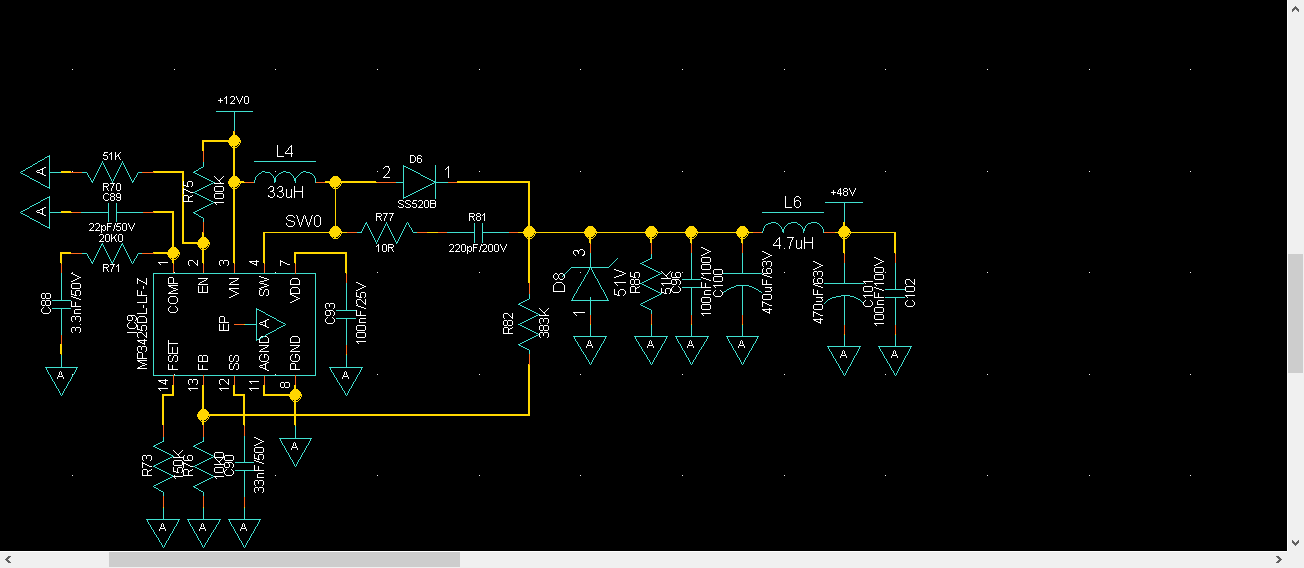
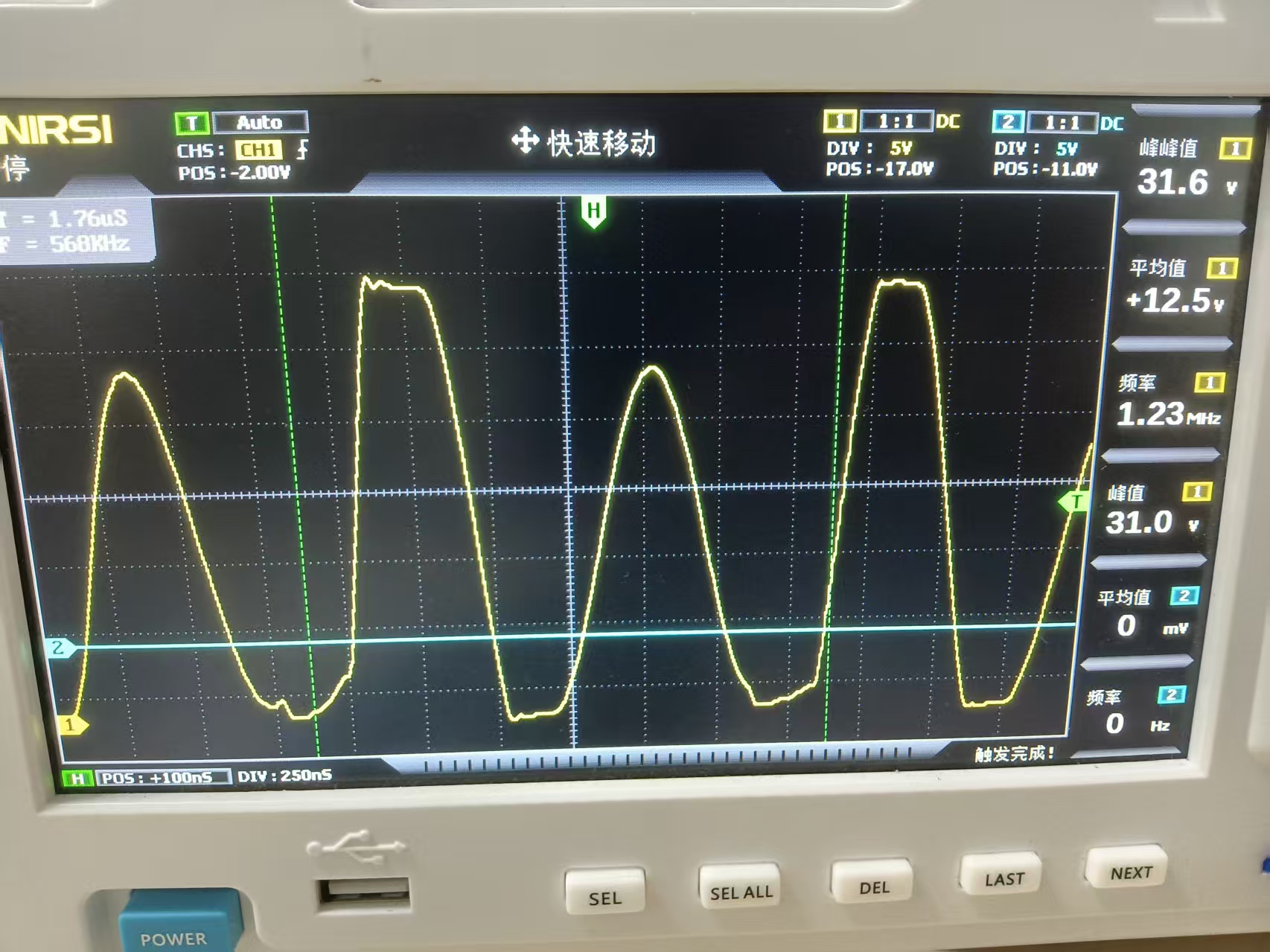
Hello, the 12-48v circuit I designed is as follows. After simulation verification, the output after production is only 37V. Why is that? Will there be any impact if I don’t add an input capacitor? And the voltage waveform of my SW port is shown in the figure. Has magnetic saturation occurred? Should I change the switching frequency? Thank you.
Hi,Fox
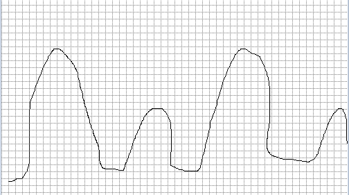
I need to figure out why such a current waveform occurs, whether a square wave should appear at the SW port, and whether the flattening of the bottom of the voltage waveform indicates magnetic saturation in the inductor.
Can you share the schematic file with me from email? Or the sw node waveform from the simulation software. I will help you figure out why it happens.
If you didn’t put the input cap, it is really possible to make your sw node really noisy. I will suggest you add the input cap first and do the simulation again. But if you can share the schematic with me it will be better. I will contact by email.
Hi Fox,
Thank you for your enthusiastic help. The voltage waveform in the second picture was hand-drawn by me on the drawing software and it is the voltage waveform measured by the actual product. It has shown a phenomenon of bottoming out. The input voltage is 12V and the power is 20W. The output voltage is 48V.
Hi Fox,
I used MP3425 to manufacture a DC-DC, 12-48V power module. When using the oscilloscope for testing, the switching frequency is different from the one I set according to the FSET pin. It is fixed at 1.2MHz. What could be the possible reasons? Could you analyze it for me?
I think I sent an email to you early this week. If you want, we can set a meeting to discuss the problems you have. There are many reasons for the unstable sw node. If you can reply to my email it will be perfect. We can try to set a meeting.