Hello.
I testing a MPM3695-100 Evaluation Board (EVM3695-100-BH-00E).
- Output Voltage : 1.0V (internal Divider 2:1 Mode)
- Load : 100A using Active Load
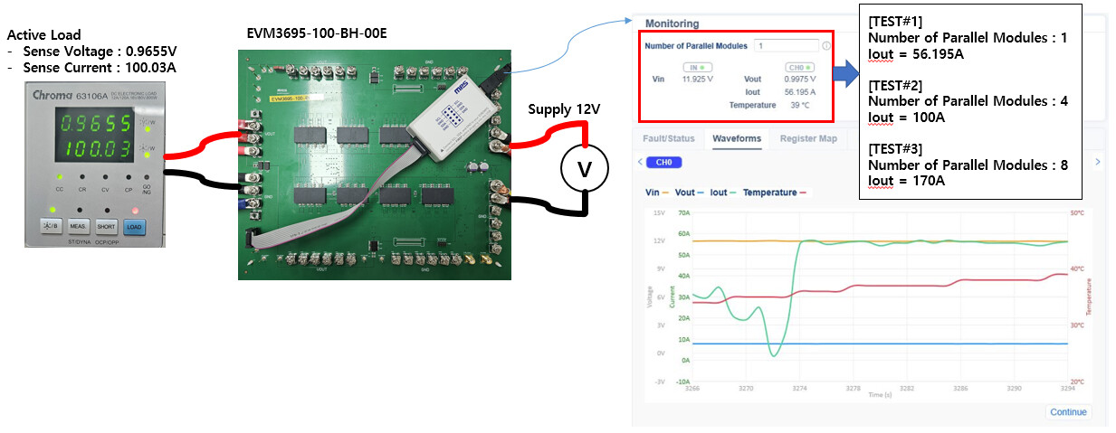
I checked operate well, 1V / 100A output at active load sensing.
I have a few questions as below.
-
Monitoring Iout Value on GUI.
When Number of Parallel Modules = “1”, IOUT = 56A.
When Number of Parallel Modules = “4”, IOUT = 100A.
When Number of Parallel Modules = “8”, IOUT = 170A.
I think Number of Parallel Modules is “8” because BH-00E.
Is it problem with the Eval Board I have or other reason?
Can you provide the exact final BOM of BH-00E for confirmation?
-
IOUT Calculation Method.
READ_IOUT Register (8Ch) : 0x27D
Output Current : 0x27D x 62.5mA = 42.0625A
How can I calculate the actual output current (100A) from the value of the READ_IOUT register?
How does the GUI calculate the current from the number of modules connected in parallel and READ_IOUT register?
-
OCP Operation.
If I wrote “Valley Current Limit = 12A”, is the current operating OCP 12A x 8 Parallel modules = 96A correct?
So, is it correct that OCP operates at 8x the register setting?
Thank you.
Juwan.
Hey @jwchang! Welcome to MPS Forums.
I see that you have already gotten support on the first two parts of your question. But to answer the third question, the MFR_OC_PHASE_SET register sets the inductor valley current for each phase. More information on this register can be found on page 41 of the MPM3695-100 datasheet.
So you would be correct assuming all parallel registers per phase are configured correctly.
Best,
Krishan
Hello Saquib.
Thank you for your answer.
First of all, I would like to check the BOM of BH-00E.
I’ll ask you after that about other issue such as current sensing.
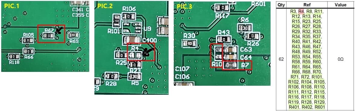
- R67 not found in BOM for PIC1.
R67 is current 0ohm on the board.
I think R67 is 0ohm right.
- R4 on PIC2 is currently OPEN on the board.
R4 of the BOM is 0ohm.
I think R4 should be modified to 0ohm, not OPEN.
- R7 is 10ohm, R10 is OPEN (PIC3)
Originnaly it was 1Kohm, but I modified it for the use of the internal divider.
The above three are different from the BOM.
Did I modify it correctly?
And please let me know if there is anything else I need to check.
Thank you.
Juwan.
Hello krishan.
I understood about the OCP setting in the case of 8 parallels.
I’ll solve other issues and proceed the test about OCP too.
I’ll ask you if I have a issue while proceeding.
Thank you.
Juwan.
Hello @jwchang
- Yes, R67 should be 0 ohm.
- Yes, R4 should be 0 ohm and not OPEN.
- R7 and R10 can be calculated by this formula
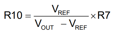
where Vref can be adjusted between 0.5 V and 0.672 V.
Please let me know if you have any questions.
Best,
Saquib
1 Like
Hello Saquib
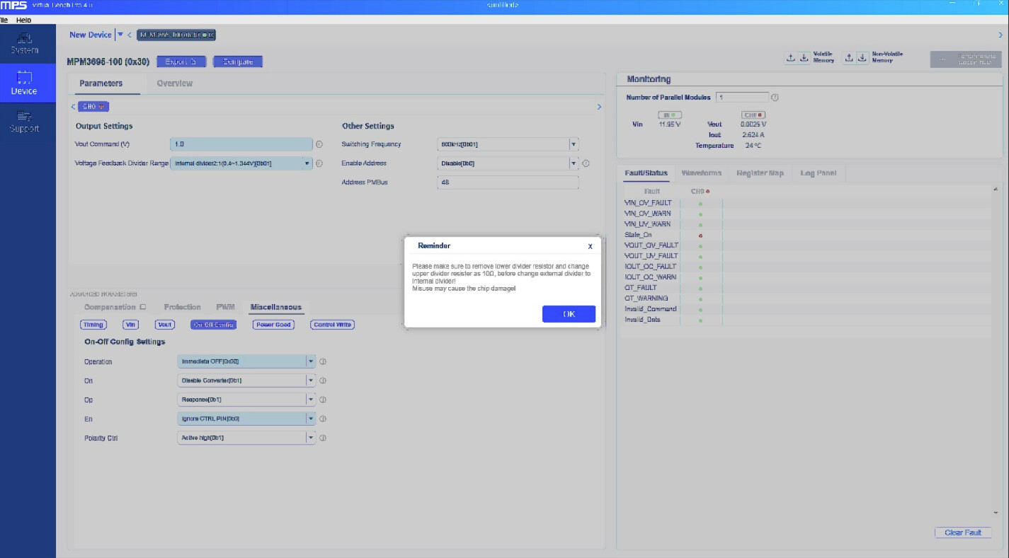
I using the “Voltage Feedback Divider Range : Internal Divider 2:1 (0.4~1.344V)”.
I checked the Reminder Message on GUI.
[Reminder]
Please make sure to remove lower divider resistor and change upper divider resistor as 10ohm,
before change external divider to internal divider!
Misuse may cause the chip damage!
Depending on the message, R10 is OPEN and R7 is 10ohm.
Is it correct?
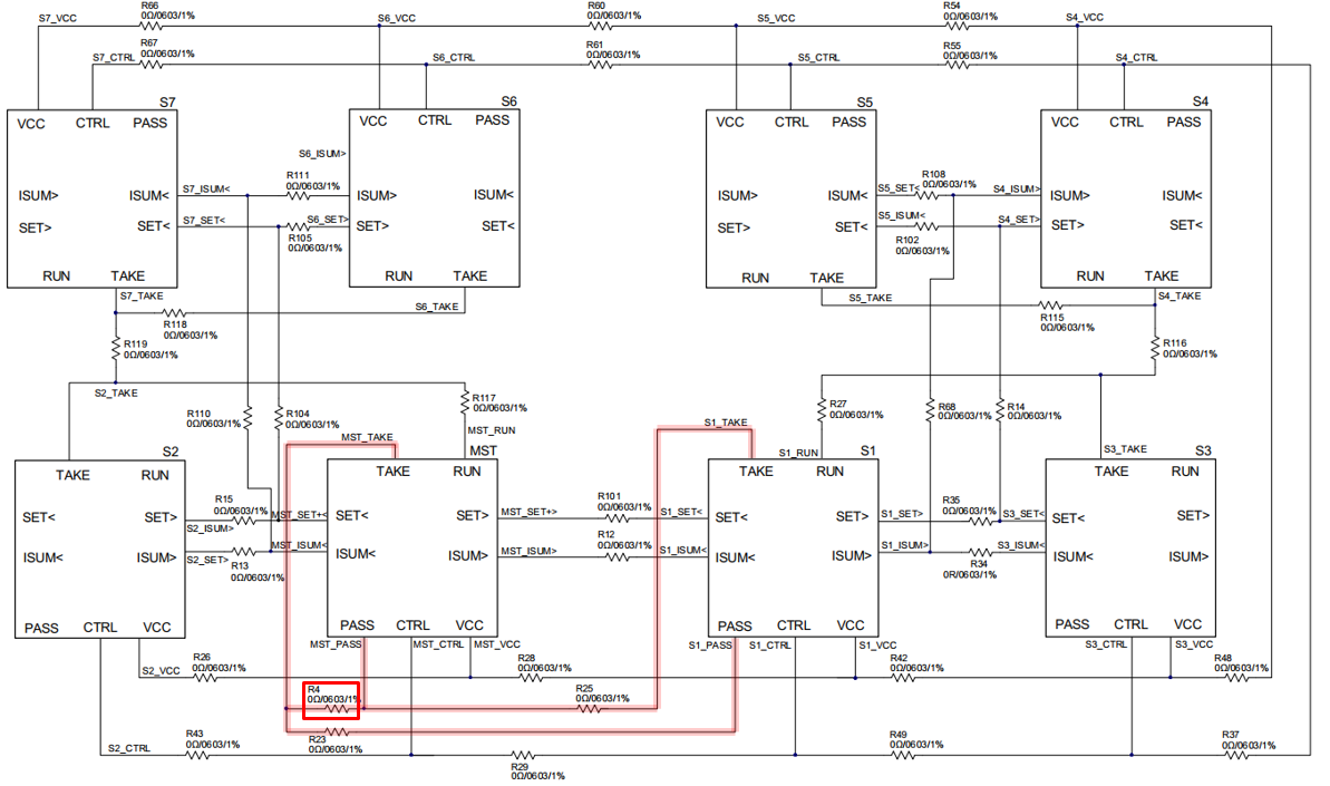
And, I assembled 0ohm on R4.
However, the operation is strange.
For example, the input voltage is well entered at 12V, but the indication is 24V and 12V back and forth.
I think data of PMBUS interface is broken.
Anyway, R4 is 0ohm correct?
When R4 is connected as shown above, both the PASS pin and TAKE pin are shorted.
Is it normal? Please confirm again and let me know it.
Hello Saquib
I have one more question regarding output current calculation.
This is when it is operated with an output of 1V/100A as shown above.
The current values measured in the GUI according to the “Number of Parallel Modules” setting are as follows.
When number of parallel modules = “1”, IOUT = 56A.
When number of parallel modules = “4”, IOUT = 100A.
When number of parallel modules = “8”, IOUT = 170A.
At this time, the value of the READ_IOUT register is 0x27D.
How do I calculate the value of IOUT displayed on GUI from the value of READ_IOUT(0x27D)?
Please explain how to calculate the IOUT value displayed on the GUI.
Thank you.
Juwan.
Hi @jwchang
You can use R10 as open and R7 as 10 ohm. R4 is 0 ohm and it shouldn’t cause any problem.
Best,
Saquib
Hi @jwchang
If your READ_IOUT register is 0x27D which is 637 in decimal. So the output current= 637*62.5m = 39.8125 A.
Hope this helps.
Best,
Saquib
Hello,
Adding on to what Saquib said, if you are using this part in multiphase application, then the value from READ_IOUT in the master will be the total current for all of the phases.
best,
-Kerr
Hello all.
What I want to know is exactly as below.
I already know that the total current is 100A by the LOAD instrument.
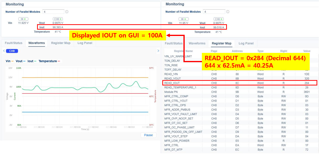
However, the value of READ_IOUT is read 40.25A as shown.
According to the above, the total current is 40.25A, which is not correct.
In addition, if the “Number of Parallel Modules” is set to “4”, the current displayed on the GUI is 100A.
How does the GUI displayed 100A with a current of READ_IOUT 40.25A?
Thank you
Juwan
Hello,
That is definitely unusual. I know that the READ_IOUT on the master chip is supposed to give the total current for all the phases. I think that it is possible that you are not talking to the master chip but instead you are looking at one of the slaves. The datasheet does not say what the READ_IOUT will represent in the slaves. Could you check the READ_IOUT in all four chips and verify that all four of them read the same?
Please let me know what you find.
Best,
-Kerr
Hello, Kerr
I changed the Address Resistor" differently to read “READ_IOUT” of each phase.
And I confirmed that the address was assigned in the GUI.
But I can’t read the value of slaves other than master.
The value of slaves is displayed as an strange value, such as 0xFF.
I’ll look at it more as I conduct further experiments regarding the problems.
In the figure of the question above, the IOUT value of the GUI is 100A.
Please explain to me how GUI displays IOUT(100A).
Hi Juwan,
I am working on getting you an answer to your question from people who know more about this part. I will get back to you as soon as I know more.
Thank you,
-Kerr