Hi all,
I am designing product which has battery charger to charge the battery. Powering the board with adaptor and board is having USB C connector in it. But USB C is having only power and ground lines, No data lines in it. is that USB C provide complete 2-3A to the board?, is there any standard protocol for the USB C to provide current of 2-3A?
Kindly let us know
Hi gururaja,
Thank you for using the MPS technical forum.
To better help ya with the question, can you kindly let us know which MPS component are you using?
Regards,
Nouman
HI Nouman,
Thank you for your reply.
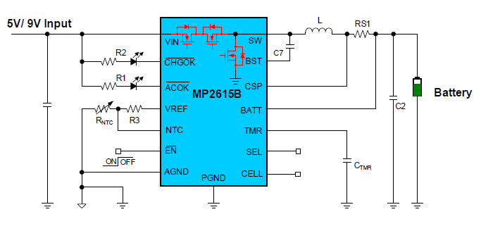
Find the MPS part number: MP2615B.
Thanks
Guru
Hi Guru,
USB-C power cables current ratings are within 3-5A. Therefore, in your application, 2-3A can be supported.
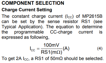
Although USB-C cable is rated for higher amperage, please note that the Icc (constant charge current) max rating is only 2.2A. To set this programmable charge current to 2A, select Rs1= 50m-ohms.
Regards,
Nouman
Hi Nouman,
selected the Rs1 = 50 ohms and your saying even I can use USB C connector to deliver the 2A without D+/D- lines with MCU? but USB cable should support of 2A current rating?
Thanks and regards,
Guru
Hi Guru,
To better understand the application, what are you highlighting in the diagram you sent?
Can you also please verify the type of cable connection you are using? Which version is it?
→ Is it USB-C end to end or USB A to USB-C?
Yes, the USB-C cable will support up to 2A. Some USB types have lower current rating. If you are only using it for a charging application. I was mentioning to not go above Icc = 2.2A because that is the max current rating for constant charge current. I will need further clarification on how you are utilizing the the data lines D+ and D- with your MCU.
From the datasheet -
Thanks,
Nouman
Hi,
I suggest you to read the USB type-C and power delivery specifications.
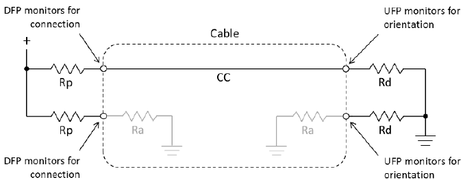
USB C source uses a pull up resistor (Rp) and the sink uses a pull down (Rd) resistor on CC pins of USB C connector.
Rd value is usually 5,1K and Rp could be 56K, 22K or 10K.
56K: default USB power
22K: 1.5A
10K: 3A
For USB-PD is a bit more complicated.
Best regards,
Pablo
1 Like
Hi Nouman,
To better understand the application, what are you highlighting in the diagram you sent? - Shared because in our design, we are using RS1 = 50 Ohms.
USB cable is USB C- to USB-A_->5V adaptor.
we are using the USB C connector in our board without D+/D- lines connecting to MCU, will this USB C connector will provide 2A current to whole circuit?
Thanks and regards,
Guru
Hi Guru,
Thank you for clarifying the type of cable you are using. For USB-A, its typically used for peripheral interfacing (example: mouse or keyboard) and the current delivery is lower. They are much lower than 2A.
Therefore, no, it will not be able to support your application and provide 2A.
USB-A to USB-C are used for phone charging application for instance, and in those cases current delivery ratings are between 0.5A or 0.7A.
Regards,
Nouman
HI Nouman sir,
Thank you for your information.
Could you provide the cable details, which delivers the 2A using USB C cable on one o side and other side?
and could you suggest us which USB combination will deliver the 2A?
Thanks,
Guru
Hi Guru,
I suggest USB-PD for power delivery.
Majority of USB-C to USB-C end to end cables should work, and be able to deliver 2A.
Regards,
Nouman
HI Nouman sir,
USB C connector on PCB with USB-C to USB-C cable work for 2A PD?
Thanks and regards,
Guru
Hi Nouman sir,
Kindly reply us, and let us know generally, everyone will use the USB C to USB A cable, should we change circuit or need to use same type cable (USB -C to USB-C) with our adaptor?
Thanks and regards,
Guru
Hi Guru,
My apologies on not seeing your response earlier.
This is application specific. But yes, because USB-A does not support high current (2A). You need to make the connector adjustment on your adapter board to support USB-C.
Regards,
Nouman
HI Nouman sir,
Thank you for your support.
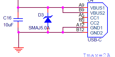
But we are not making the adaptor, and find the schematic for the USB connector which is using in the our PCB.
Part number of the connector is USB4125-GF-A
kindly provide solution for it.
Hello Guru,
This part is not a MPS component. We can not provide assistance on the forum for non-MPS parts.
To guide you to the solution you need, please look at the connector’s datasheet. The current rating is listed.
Kind Regards,
Nouman
HI Nouman sir,
Thank you for your support.
Seen in the datasheet of it, its only for charging purpose.
Could you suggest any MPS part number for it.
Thanks and regards,
Guru
HI Nouman sir,
If MPS having the RTC IC with integrated coin cell, Please let us know.
Thanks and regards,
Guru
Hi Guru,
Few suggestions is to look into our Battery Management Products, we have quite a variety of them.
I would like to suggest the MEZS7-1SSAPowerBank Module.
Regards,
Nouman
HI Nouman sir,
Thank you for your support.
Seen in the datasheet of it (USB4125-GF-A), its only for charging purpose.
Could you suggest similar spec MPS part number for it.
and RTC IC with integrated coin cell.
Thanks and regards,
Guru