What is the intended method of configuring devices using the Virtual Bench Pro 4 GUI?
My current setup is using the EVKT-USBI2C-02 to connect to my boards I2C bus which has a couple of MPS54524s.
Currently, I am performing the GUI actions based on the device datasheet, so:
1. Drive the EN pin to low
2. Turn on the 12V power supply
3. Write to Volatile Memory
4. Cycle the EN pin low-high-low to check that the correct configuration is being used
NOTE! This sometimes enables the device in the way I expect it to, and sometimes with the default settings.
5. Write to Non-Volatile Memory
6. Cycle 12V power
7. Cycle the EN pin low-high-low to check that the correct configuration is being used
NOTE! This sometimes enables the device in the way I expect it to, and sometimes with the default settings.
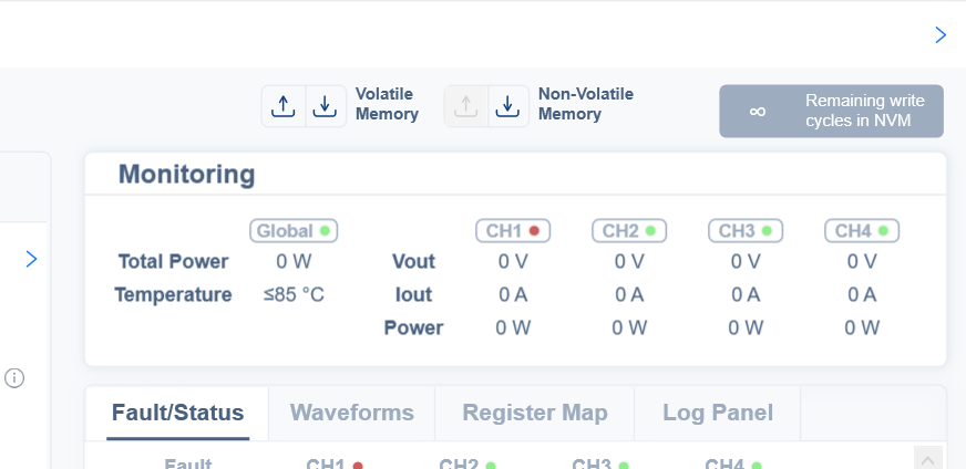
The “Write to Volatile Memory” and “Write to Non-Volatile Memory” actions are performed by pressing on the downward-facing arrows near the top-right corner of the GUI.
I have tried:
a. Wait for a few seconds in between each step, including the GUI pop-ups that claim that programming was successful.
b. Skippin the “Write to Volatile Memory” action just in case that messes something up, with no change to the end result.
The full cycle eventually works, so my question is: Am I doing something wrong?
This is extremely frustrating, and it should not be this hard to evaluate if the device has been configured properly!
I can understand your frustration. You will want to make sure that you write to non-volatile memory for settings that you want to save. Before writing to non-volatile memory with all desired settings, please ensure the following:
The MPM54524 is powered on and powered by your input.
The MPM54524 is enabled during non-volatile programming.
After writing, try reading to see what you get.
Feel free to power cycle and see if these register values saved.
Let me know if this worked. While this isn’t outlined anywhere, I just want to make sure things are consistently being written correctly. If I may ask, where is this 7-step procedure that you have outlined? I was not able to find this MTP sequence in the MPM54524 datasheet.
The MPM54524 is powered on and powered by your input.
The USB-to-I2C dongle that I mentioned successfully finds the devices when I start the GUI, so I feel safe in assuming that they are.
The MPM54524 is enabled during non-volatile programming.
I am getting a little bit concerned by this statement. Both the device datasheet and the GUI is telling me to make sure that the EN pin is pulled down, i.e. the device is disabled.
If I may ask, where is this 7-step procedure that you have outlined?
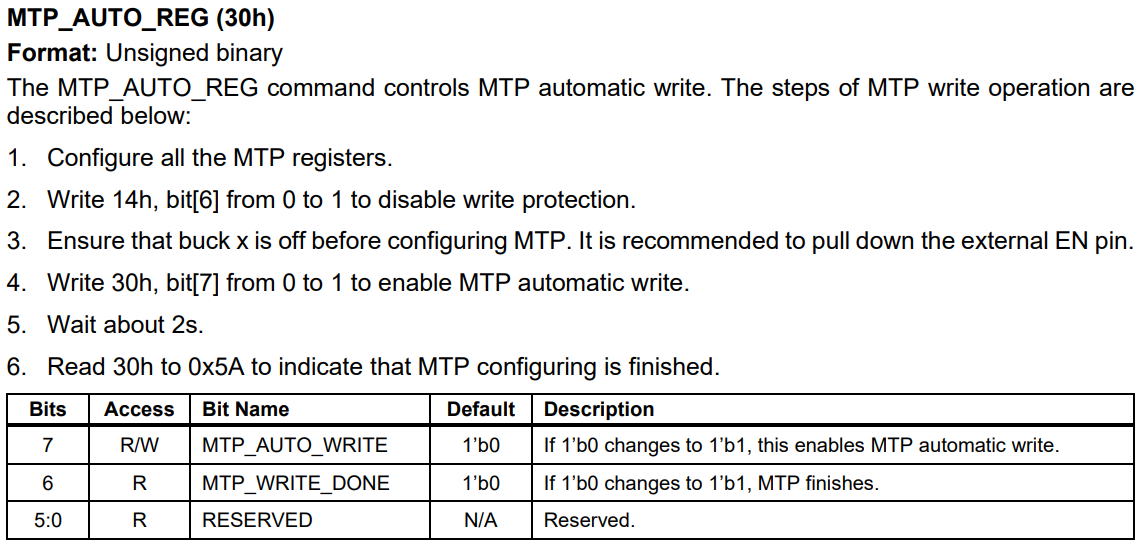
I may be reading an out-dated version of the datasheet (Rev. 1.0), but the “NVM write” sequence that I am referring to is outlined under the “MTP_AUTO_REG” register definition, on page 45.
It also clearly states that the EN should be held low to disable the outputs.
Other than that, my procedure is 7 steps just to make sure that I don’t accidentally damage any devices. That is why I start by holding EN low, as otherwise, it seems like the default output voltage is 3.345V, which would instantly destroy at least some of the devices on my board.
This also means that I can’t enable outputs until after I have written to the volatile memory.
PS. Something I didn’t mention in my initial post is that for all “write” actions performed in the GUI, I always get a green checkmark. If there is anything that didn’t go as expected due to hardware issues, I would expect some sort of error message.
PPS. It would also be good if there was a setting somewhere to enable debug info. In this case specifically, it would be nice to read back the registers without overwriting my project settings, so instead of just injecting the values into the corresponding fields, maybe have a popup that lists the differences, or something along those lines.
I apologize if that already exists. I am having a really hard time finding detailed documentation on how to use the Virtual Bench Pro 4 GUI.
In the meanwhile, I have been trying to trigger a write to MTP using raw I2C commands.
Am I understanding correctly, reading the MPM54524 datasheet, that I should:
Write the desired values to the volatile memory registers.
Write 14h, bit[6] from 0 to 1 to disable write protection.
Ensure that buck x is off before configuring MTP. It is recommended to pull down the external EN pin.
Write 30h, bit[7] from 0 to 1 to enable MTP automatic write.
Wait about 2s.
Read 30h to 0x5A to indicate that MTP configuring is finished.
Which should end up taking the data that I wrote to the registers in step 1, and write that data into NVM.
I did this while holding the EN low, since I can’t allow the bucks to output until they are properly configured.
Holding the EN low seems to align with step 3 in this case, wouldn’t want to damage anything downstream as you mentioned. I agree that there should be a more active debugging window on Virtual Bench Pro 4.0, this will surely be implemented in the 5.0 version to come.
Now that I am on the same page (in a literal and figurative sense), I feel that the core issue could be a timing/power sequencing requirement not being fully met OR the GUI isn’t properly implementing non-volatile memory writes despite showing success:
Follow the datasheet procedure where you do the following:
Keep EN low during the entire configuration process (as stated in register documentation)
Write to volatile memory first
Then write to non-volatile memory
Power cycle (including T2V power) before enabling any outputs
Add these verification steps:
After every non-volatile memory write, try power cycling completely.
Then, reconnect and check if settings persist before enabling outputs.
Considering the timing:
Add longer delays between 5-10 seconds as opposed to the 2 second delays after non-volatile memory writes.
Ensure that T2V power is stable before proceeding. This is simple and redundant, but best to be sure.
Additional Debug Advice and Comments:
Try to verify that all I2C commands are being sent by looking at logic signals.
Try writing to non-volatile memory with just the MPM54524 alone to perhaps further isolate any issues in the system.
If none of these issues work, interfacing with I2C on a lower level to program the registers would be best.
I know I threw a lot at you just now. Take things one step at a time and let me know if there are any updates.
Understood, as long as you are able to reliably interface following the datasheet process, then the subject matter of this post is resolved, and this post shall be closed. Please reference this post and create a new one if anything changes.