It is unclear, to me at least, that I can actually program, using the PMBUS, the entire range of VOUT without changing the VOSNS resistors. For example, I want to be able to set VOUT to 1.8V, or 2.5V or 3.3V as needed by the particular board that is plugged in that this module would power, without any hardware modifications, just over the PMBUS. Is this do-able or not? And if it is do-able, how can I do that using Virtual Bench? In the VOUT field it will only allow input between 1V and 1.344V.
Looks like I need to adjust the VOUT Scale Loop. Is this the right way to do what I am trying to do? I’ll check for a formula in the datasheet…except that the datasheet claims the Vout Scale Loop can only be set between 0.5 and 0.672V, yet I was able to set it to 0.2 and the output is now 3.3V.
[Update] Looks like the right way to do this is to use internal divider, change the external resistors to lower removed, and upper to 10 Ohms. That should allow me to set any voltage via PMBUS, just need to select the correct internal divider. Is that correct? I could not find any info on the FB resistors update needed to use the internal divider in the datasheet. A popup when I changed to internal divider in Virtual Bench told me to do this in order to use the internal divider.
Hello Austin,
You are on the right track in terms of using the internal divider. Although when I have used the GUI, I received the following message when making adjustments to the external divider when using the internal divider:
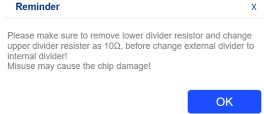
Double check this message on your GUI interface regarding the internal divider.
Hi Krishan,
Thank you for the reply. Yes, I got that same popup message, which is the only way I knew about removing the low side resistor, and changing the high side resistor to 10 Ohms. I am surprised that information is not in the datasheet.
I also have the -20 EVM. The -20 is supposed to go up to 5.5V output, but in the GUI, it is limited to the same 5.326V (or what ever it is) that the -10 is limited to in the GUI. How can I get 5.5V out of the -20 using the GUI, or is this a GUI bug? Or, does the -20 not comply with the spec and allow for 5.5V when using PMBUS?
You should be able to achieve a 5.5V output with both the -10 and -20 modules. Make sure you are using the correct Internal Divider (as they don’t all have the same range).
Also, ensure that your VOUT_SCALE_LOOP is also correct and matches with what the expected output voltage since this has a direct relationship with the feedback voltage.
Another line of questioning would lead me to ask about the loading conditions here. Is this unloaded? If not, how much of a load do you have here? Is there a difference in voltage when measuring Vout_sense +/- pins with a multimeter?
Best,
Krishan
After ensuring these variables, are you still not getting 5.5V?
The GUI won’t let met set 5.5V as Vout. Only as high as 5.376. It’s also the highest voltage listed on the internal divider list, which is the div 8 option. Is this a bug in the GUI?
I am also measuring Vout with a DVM at the VOUT connection.
Just double checked the datasheets, apologies for misremembering this detail as I was looking at the -20 datasheet (this is something I’ll make a habit in checking this first from now on).
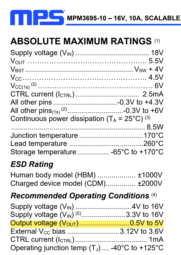
The maximum recommended output setting for the -10 is 5V, so this isn’t some bug in the GUI.
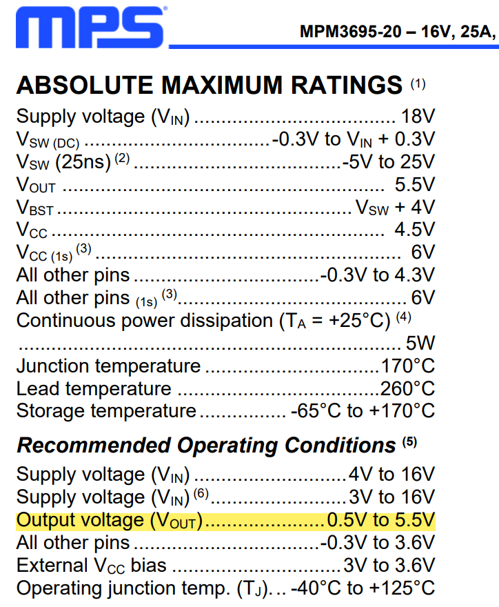
For the -20, the maximum recommended output voltage goes up to 5.5V max.
Looks like you’ve been pushing the -10 to the limits here in that case. But since the absolute maximum voltage there is 5.5V, you are still regulating.
Hope this explains some things.
Best,
Krishan
That’s what was relying on, was the absolute max on the -10, and the max operating on the -20, both should be able to go to 5.5. But, as I said, the GUI will not let me do that. Are you able to try the GUI on a -10 and -20 to see what I am seeing?
Note, on Table 1 of the -20 datasheet, it claims the limit is 5.376V.
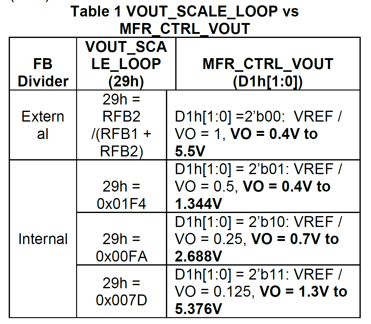
It looks to me like the issue is when Vout Scale Loop is set 0.125, as is done for the last option there, the highest is 5.376V. It would need to have Vout Scale Loop set to a lower value, such as 0.120 in order to allow Vout to be 5.5V via PMBUS.
Given the limitations of VOUT_SCALE_LOOP for the internal dividers for the -20, it seems that you can only reliably get an output of 5.5V with external resistors. Have you tried this yet? Does your design allow for this?
I can’t speak on or recommend this for the -10 as you would be operating at the absolute max voltage here.
For the 5V converter, I need to be able to margin it +/-%10. So I may be able to use external resistors to set the output to 5V, but can I then go from 4.5V to 5.5V using the PMBUS Vout margin high (and low) to get that range? This is why I bought the eval boards, to make sure one of these did exactly what I wanted it to do before I committed the design to using these.
I would think I could program internal divider, but program the VOUT_SCALE_LOOP to 0x0078 (120D). I can do direct register writes to see if that works. I think the 5.376V is a GUI limitation, because someone chose to fix the VOUT_SCALE_LOOP at .5, .25 & .125 for the three internal dividers, instead of letting the user choose to change those.
I see, makes sense. I’ve never seen that used in application, but you could do this as you’ve described with the external divider and vary VOUT_SCALE_LOOP to achieve the +/- 10% margin range. Makes complete sense buying those eval boards.
You can try direct register writes as well with the internal dividers. Keep me updated on progress here if there are any additional questions.
I updated the two resistors (removed R2, changed R1 to 10Ohms) I can set voltages as I want, with the exception of the 5.5V. When set to internal divider, the 0x29 register can not be directly written it appears, from the GUI. BUT…my guess is when I have my own code running that programs these converters, I can do any register write I want. Are there any sample C source code, or libraries, for accessing this converter? Is there a way in the GUI to override this disallowing me to update register 0x29?
Best Regards,
Austin
[Update] Register tool lets me update register 0x29 to 0x78. But, updating the Vout won’t let me go past 5.38V…0x0AF8. Anything higher than that to loc 0x21 and the output goes to 1.2V! This is on the -10 BTW. I can try this on the -20 and see if it’s any different…tomorrow.