Dear MPSer,
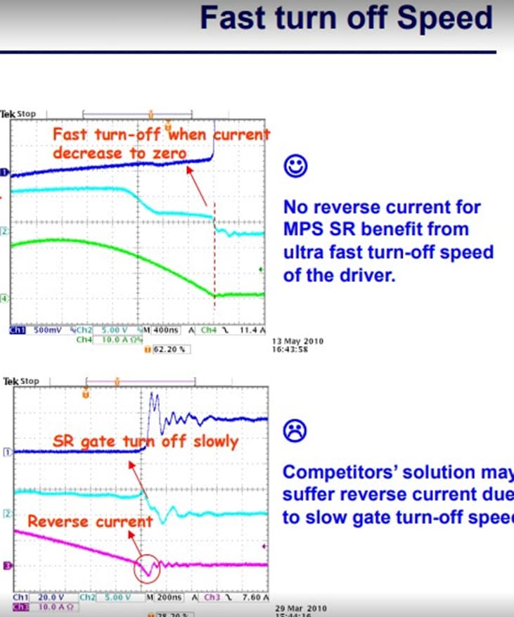
As MPS’s presentation, I would like to discuss the SR’s MOSFET VDS oscillation when SR turned off.
My question is why the suffer current reverse when turned off slowly? And the phenomenon only happen in fly-back convertor?
Dear MPSer,
As MPS’s presentation, I would like to discuss the SR’s MOSFET VDS oscillation when SR turned off.
My question is why the suffer current reverse when turned off slowly? And the phenomenon only happen in fly-back convertor?
Not MPS, but all rectifiers have to switch from conducting to non conducting as the voltage across them reverses. Diodes are smart enough to do this on their own but even with diodes you have fast ones and slow ones and varying amounts of reverse current and varying suitabilities for high frequency switching power supplies. Mosfets need to be controlled to turn on and off. In the off going transition two things have to happen, the controller needs to figure out that the current in the diode is about to reverse, and then secondly it has to act fast to limit the reverse current. The better the controller does both things, the more ideal a diode is created by the ideal diode driver.
Thank you very much!
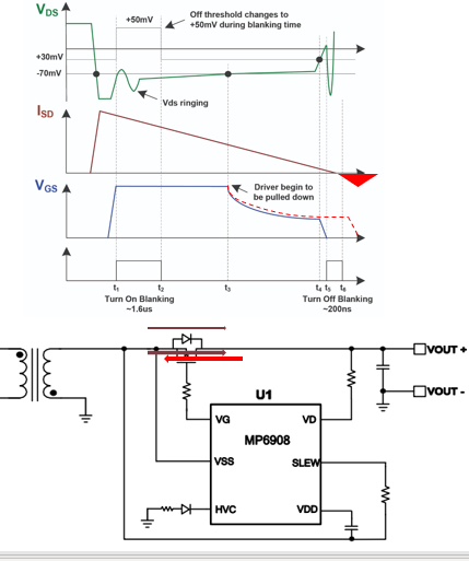
I afraid that I may have not fully understood your explanation, could you help me to confirm if I’ve interpreted it correctly as following figure.
also that, could you let me know the mechanism of reverse current generation.
In flyback the mechanism of reverse current generation is as follows. During the ON period of the primary side FET energy is stored in the transformer, the phasing is such that during this period the secondary side rectifier is reverse biased. Once the primary side FET switches OFF the voltage on the windings both primary and secondary flip polarity and the secondary side rectifier begins to conduct. The energy that had been stored in the transformer discharges into the output cap through the rectifier the rectifier is ON. In a DCM or boundary mode flyback this energy fully discharges the current from the transformer falls to zero. Once the energy in the transformer is gone, the voltage across it collapses so now you have an output capacitor (fully charged) and a transformer secondary with no energy in it. Current then begins to flow backwards through the rectifier.
Alternatively in you little picture the line Isd will just keep going negative unless the rectifier switches off to stop it.
Dear Jshannon,
Thank you very much!
Such as LLC converter has dead time in half bridge, Is this reverse current also the generate of the output capacitor?
The LLC primary side switches are a little different. The operating frequency is chosen so that the load appears “inductive”. What that means is when the active switch turns off the inductive load attempts to force current to continue to flow. For the high side switch that means the inductive kick forces the voltage low. The switch node is naturally commutated by the inductance. If halfway through that natural transition you decide to hurry it up by switching on the low side fet you will incur losses due to discharging the node capacitance in a dissipative way through your fet rather than a lossless natural ring down with the inductive energy.