Hi,
We want to integrate MP5470 PMIC to PSOC microcontroller through I2C interface and need to configure the output voltages of 4 channels and need to perform efuse programming for storing these configurable output voltages in non-volatile memory of PMIC through I2C lines of PSOC. Can you please suggest how to program the efuse programming and say if there are any registers corresponding to that efuse programming and please provide if there are any such programmable registers.
Hello,
Just to clarify my understanding of your request, you would like to know which registers to access for programming the output voltages and save those configurations in non-volatile memory? Is my understanding correct?
Registers 0x40-0x4B can be used to configure the voltage rails for Buck’s 1-4 for MTP. As an example, to set the output voltage of Buck 1, you can access the Vout_Select register (0x42) and bit D[7]. This is used to set the internal divider ratio. Reference pg. 26 in the datasheet for more detailed information on setting the output voltage.
To write to the MTP (multiple time programmable memory), ensure the MTP_program bit (D[5]) in register 0x0E is set to 1. Reference page 19 in the datasheet for more detailed information on programming the MTP.
Hope this is able to give you some guidance.
Best,
Stephen
Thank you @Stephen.FAE for your suggestions. We want to configure 4 voltage levels of 4 banks as 1v,1.8v,2.5v,3.3v. Can you please clarify us the power sequence of the respective 4 banks. Is it ok to configure in that consecutive sequence like for bank1 it is configured to 1v , bank2 is configured to 1.8v, bank3 is configured to 2.5v, bank4 is configured to 3.3v with some delays. Can we configure the bank voltages like this or else is there any other sequence of assigning the 4 bank output voltages?
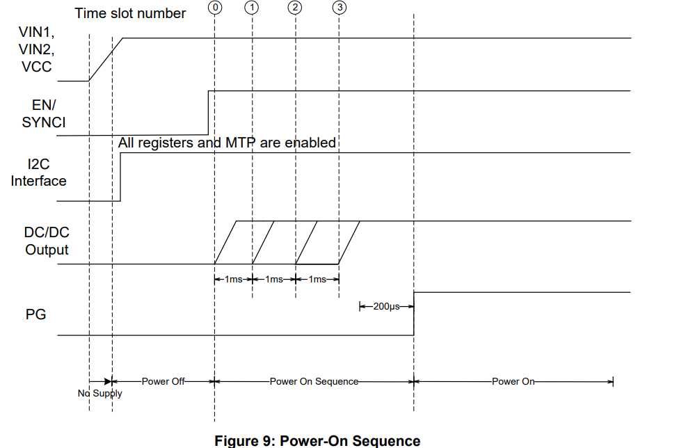
Yes, it is okay to configure the output voltage sequentially as you mentioned. By default, in normal operation mode the Buck regulators will start up sequentially, with a 2ms delay. You can adjust the delays for turning the regulators on, use the Soft-Start Delay[N] register. For example, Buck Soft Start Delay is register [0x00] bits D[5-4}, reference page 27 for other registers.
Below is a snippet outlining the power-on sequence, for your reference.

For our project, the VIN1 and VIN2 of PMIC is getting powered at the same time with the same power source. But, in the datasheet it is mentioned as for the safer side, VIN1 should be powered up first, which powers up buck 1 and buck 4. But according to our configuration, will it affect the safe mode? Do we need to give 1V to buck 1 and 1.8V to buck4? Then 2.5 to Buck 2 and 3.3 to buck 3?
The device will turn on in safe mode so that the SOC can startup safely. It will then load the MTP program into I2C registers, which take effect immediately. Once the programming is done, the MTP will start up according to the startup sequence programmed into the e-fuse.
Is the startup sequence of PMIC by default is Buck1 first, then Buck2, then Buck 3 and finally Buck 4? If yes, we may need to program 1V to buck1, 1.8 V to buck 2, 2.5 V to buck 3 and 3.3 V to buck 4, right? Is this sequence of MTP programming, correct?
Yes, the default configuration for Power on Sequence by MTP is Buck 1, 2, 3, and then 4. By default, the converter starts with a 2ms delay between each of the regulators turning on.
To answer your second question, yes would need to program each of the Buck to your desired output voltage.