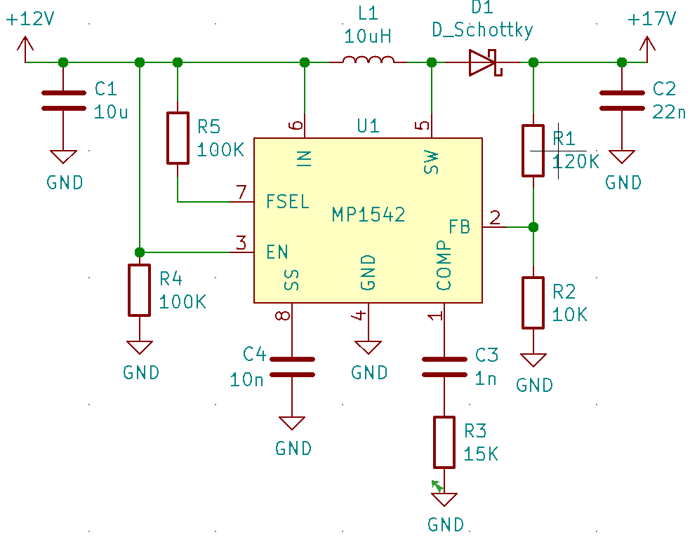
I try to follow the datasheet to build a 12V to 17V application using the MP1542. Attached the schematic I scetched for this. According to the formula I need to use R1 in the area of 120K to create 1.25V on pin 2.
But I feel like I missed something very basic here because I managed to burn a few chips already. Once I raise the input voltage to about 8V onwards, the output voltage rises and the regulator does not manage to hold the output voltage. There are only examples with lower input voltages around, like 3.3V or 5V. So does someone with more expertise in the field have a suggestion what’s wrong with this circuit?
Thx,
Oliver
Hello Oliver,
Welcome to the MPS Technical Forum!
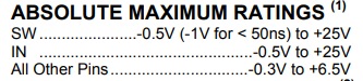
I believe you have the wrong connection at the enable pin. When Vin > 6V, a pull up resistor is required. With the current resistor configuration you have, you exceed the voltage limit of that PIN. See “Absolute Maximum Ratings”, the maxes of the enable pins are -0.3 and +6.5V. Moving the resistor up and removing the connection to ground should solve your issue.

Best,
Vinh Tran
Thank you Vinh for your swift reply which was actually super helpful. Indeed pulling pin 3 down using the 100K did the trick, everything working now as expected. Thank you so much for the hint, obviously I completely misinterpreted the description of pin 3. 
Further questions arouse on my end, if I may:
- Can I reuse R5 for EN, so that FSEL and EN share the same pull down resistor?
- What is the maximum current available at the output assuming that I would only consume the 5V difference between input and output? How to calculate this?
Kind regards,
Oliver