I am designing a DC-DC PCB that takes an input of 28V at 100W and want to output 20V at 100W (5A) in the form of USB Type C.
I was looking at your MP5031 part to implement this and noticed 2 suggested design options mentioned on your website and on the datasheet.
-
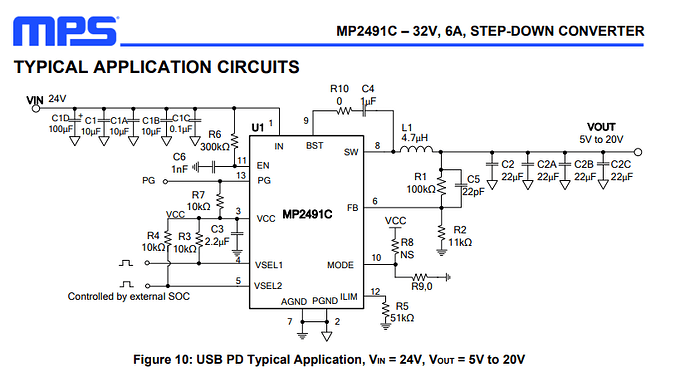
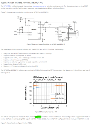
To implement MP 5031 with MP2491C for 100W, you guys recommended using below:
a. Do you have a more detailed reference schematic/design that I can follow either as an image or an Altium file?
b. What specific MP5031 part number or configuration should I be using? I am aware that these ICs are preprogrammed and thus I want to ensure I buy the right one
c. Is Programming required?
-
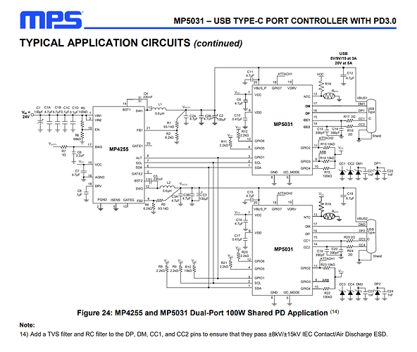
For implementing 2 MP5031 with MP4255, you recommended using the design in the MP5031 datasheet.
a. I noticed the max output current for MP4255 was 3A and 6A for dual applications. So does each individual output 100W or do they produce each 50W and 100W collectively?
b. What specific MP5031 part number or configuration should I be using? I am aware that these ICs are pre programmed and thus I want to ensure I buy the right one
c. Is Programming required?
MP5031 data sheet
- Are there any other DC-DC converters that pair well with MP5031 to produce 100W?
Hello, I will answer your questions in descending order:
- MP5031 with MP2491C
- a. The MP5031 has a few detailed reference designs that you may defer to. The following images show specific part numbers for the MP2491C and MP5031 separately (not quite to the input specs that you have). But they should provide some insight on how certain connections should be. They were found on the MP5031 datasheet and MP2491C datasheet:
- b&c. The MP5031 sometimes comes pre-programmed for specific customer, which will translate to a corresponding set of registers set and a respective differing suffix code. For your application, I believe the default version should be ok (there would be programming involved in this case depending on your own preferences). If you have a high volume of these parts that need to all be programmed or if you would like to inquire on more details for specific suffix codes, please submit a ticket to the following link as the engineers here will route you to the correct variation of the MP5031:
MPS NOW Remote Support - Support (monolithicpower.com)
- MP5031 with MP4255
- a. At 20V out for the MP4255, the part is capable of 3A for dual channels and 6A for a single shared channel output. So individually they may provide 50W and together they may provide 100W.
- b&c: Defer to the answer as outlined the previous question, as it comes to the same conclusion. And of course, programming may be required depending on desired specs.
- In order to produce up to 100W, we need a single output DC/DC buck converter with a high output voltage and up to 5A at the output. This buck converter also needs to have an SDA, SCL, and an ALT pin that are able to communicate with the MP5031 via I2C. The only product that fits those requirements other than the MP4255 would be the MP8857. However, this part is in the pre-release stage and is still in development. If your project timeline is for a while, this part appears to be an ideal choice. Otherwise, I would defer to combining the current channels for the MP4255.
Best,
Krishan
1 Like
Thank you so much for your response! I have a few follow up questions:
-
MP5031 with MP2491C
a. Since the input range for MP2491C supports 28V, we would only need to change the voltage divider right?
-
MP5031 with MP4255
- a. So to produce 100W, should we just combine the 2 VBUSes into a single rail that connects to the type C port?
- Other DC/DC Products
- a. Does the DC/DC buck converter need to be MPS to communicate with a MPS PD controller or can we get any DC/DC buck?
- MPQ4242
- a. I don’t see anywhere that this converter can support 100W input (28V). All the reference designs are for 9V-16V input.
- b. There is no default configuration that supports 20V output and 5A correct? We would need to program this using I2C
Hello,
Just wanted to follow up to see if I can get a response on my previous questions ^^^
Apologies for the delay in this response. I meant to send this response to you earlier, but it seems it was stored in my drafts. Thank you for following up.
-
MP5031 with MP2491C:
a. Yes, all you would need to do is change the voltage divider to ensure the output voltage of the MP2491C and your system should be powered up. Although the only drawback with this option is that the MP5031 wouldn’t receive I2C data from this. If that is fine with you, then this should be a functional solution.
-
MP5031 with MP4255
a. Yes, combining these rails together would yield you up to 6A total. Setting the output current of each of these rails at 2.5A and combining to 5A given Vout = 20V should yield you 100W. You would send and receive data via I2C with this option.
-
Other DC/DC Products
a. This is a good question that would also apply to the MP2491C and for any other DC/DC converter that works with your application. Reading into the datasheet, the MP5031 would just have to be in I2C slave mode to disable I2C where I2C_MODE is connected to VCC. This would effectively disable any status messages or commands delivered or received by I2C. But if this is not needed for your application, then this is all you would need to do.
-
MPQ4242
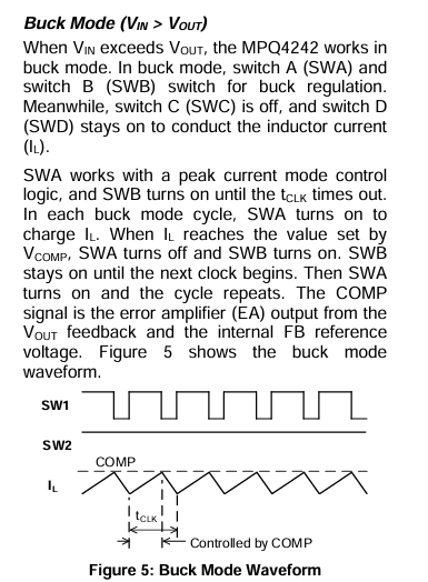
a. This is true, all reference designs in the datasheet are configured to the input of 9 - 16V. However, the part is capable of receiving an input of up to 36V as the maximum recommended voltage with 20V x 5A = 100W at the peak output.
b. Correct, to get this part working with 20V @ 5A, I2C programming would be required.
1 Like
Hello,
For MPQ4242, I have some questions about the track width for a couple of pins
- For VIN, BST1, BST2, SW1, SW2 what is the current rating and how should we size those tracks if we have a 20V & 5A input
Apologies for the late response. To answer your questions on the current ratings for each of the following pins:
- Vin should be seeing an input of 100W/28V = 3.57A, which is well below the rated input range for what Vin is designed for. This should be good.
- SW1 and SW2 should handle at maximum 5A, which is also well below the rated range for what these pins are to handle.
- BST1 and BST2 power the high side gate drivers, so current requirements at these pins are smaller than the others as they would charge and discharge the gate capacitance for the MOSFET in the MPQ4242. To be safe, currents should be within 50mA at these nodes.
In regard to trace widths, I will use an example for a single layer 1oz copper:
- VIN and all SW nodes will be subjected to 4A - 5A, so using a trace width of around 100mils - 120mils would be generous. If you have more layers on your PCB (you likely may) having trace widths of nothing less than 80mils will be sufficient.
- For all BST traces, 10mils - 15mils should be enough to handle 50mA.
Overall though, having wider traces when you can afford the space will yield better thermal results and ensure increased reliability under full load conditions.
Best,
Krishan
1 Like

