Hi,
Apologies on the late reply, Thank you for utiliizing MPS Forum.
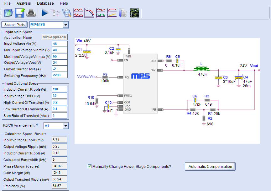
I went through this to see what the issue was. The simulation will assume ideal case, its better to follow the datasheet. You need to consider the loop bandwidth with R3/R1 sizing.
- For R3/C5 arrangement of A2, I would recommend going with A1 arrangement.
- Also, populate the polarized cap C4 on the schematic
- I think the model assumes ideal input, therefore, C1 caps is 2.2, It should be higher.
- Because of your operational spec, your output can be in DCM mode with the schematic you have shown.
- You may also download the DCDC designer for desktop version
For future reference:
- You may refer to my values here as well.
Kind Regards,
Nouman